Both lights then pass through the finger and are “read” by the receiver. As these lights pass through the finger, a
proportion of the light is absorbed by the blood and by the soft tissue, in function of the concentration of haemoglobin.
The quantity of light absorbed, at each frequency, depends on the degree of oxygenation of the haemoglobin inside the
soft tissue.
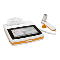
2.2. DISPLAY MODULE
The display module shows patient data, user set parameters and test results..
It is connected with:
40-pin flat-cable for digital connection (code 512584)
The lamp controller (IC6) MAX 8822
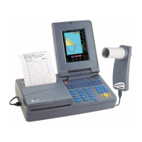
2.3. PRINTER MODULE
The printer module gives a printout of the patient data and spirometric/oxymetric results. The printer is a thermal printer
and requires thermal printing paper.
The printer is connected to the mainboard via 3 cables:
- a 4-pin flat-cable for driving the motor for paper advance
- a 4-pin flat-cable for the sensor, that checks that paper is inserted
- 28-pin flat-cable for supply, data transmission and checking the temperature of the printer head, to avoid overheating.
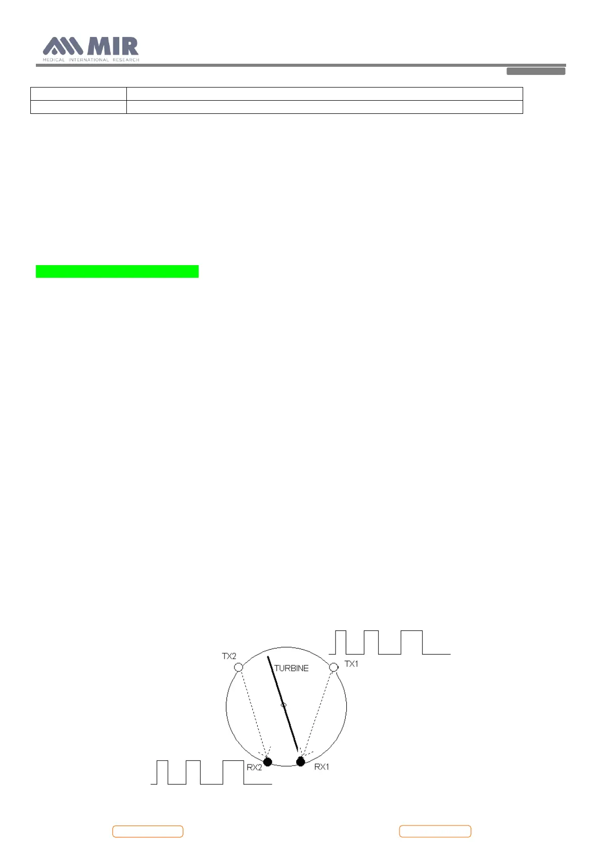
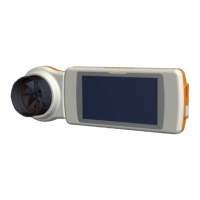
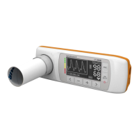
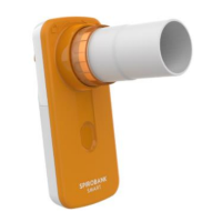
2.4. TURBINE FLOWMETER
The sensor for measuring flow and volume is similar to the model already used in other spirometers produced by MIR
(Series MIR 040 Mod. Spirodoc, MIR024_REV2 Mod. Spirobank G USB, etc).
The turbine flowmeter consists of one mechanical and two electrical parts:
Mechanical parts:
- turbine
Electrical parts:
- Two pairs of infrared transmitters/receivers positioned as shown below.
- A signal conditioning circuit to rectify the output signal from the two infrared light receivers.
The rotation of the rotor causes the interruption of the infrared beam, thus creating a pulse signal which has a frequency
directly proportional to the flow.
The measurement of the air flow which passes through the tube is therefore proportional to the number of interruptions
of the infrared beam.