MELSEC-A
4. INSTALLATION AND PRE-OPERATION SETTING PROCEDURE
4 - 5
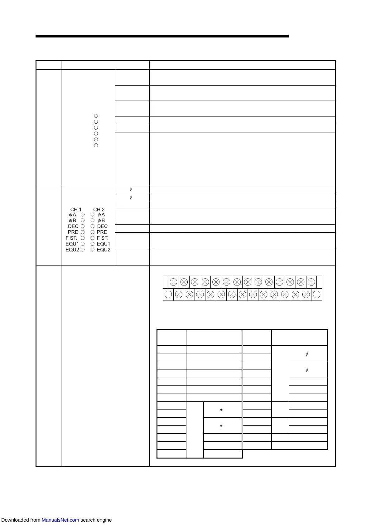
Number Name Description
6)
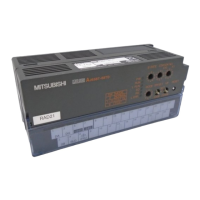
LED indicators
PW
On: Power on
Off: Power off
PW
RUN
L RUN
SD
RD
L ERR.
RUN
On: Normal operation
Off: 24VDC power off or WDT error
L RUN
On: Normal communication
Off: Communication break (time excess error)
SD Lit to indicate data transmission
RD Lit to indicate data receive
L ERR.
On: Communication data error (CRC error)
Flashing at constant interval: Station number settings and baud rate settings are
changed during power supply.
Flashing at non-constant interval: Termination resistor is not provided or the unit
or the dedicated cable for CC-Link is subject to
noise.
Off: Normal communication
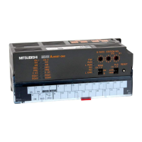
7)
LED indicators
A Lit to indicate that voltage is being applied to the phase A pulse input terminal.
B Lit to indicate that voltage is being applied to the phase B pulse input terminal.
DEC Lit to indicate down count.
PRE
Lit to indicate that voltage is applied to the PRESET terminal, and remains lit.
Turns off on the trailing edge of the external preset detection reset command.
F ST. Lit to indicate that voltage is being applied to the F.START terminal.
EQU1
Lit to indicate that the coincidence output setting No. 1 is equal to the counter
value.
EQU2
Lit to indicate that the coincidence output setting No. 2 is equal to the counter
value.
(The AJ65BT-D62D-S1 does not have this LED.)
8)
Terminal block
1 3 5 7 9 11 13 15 17 19 21 23 25 27
2 4 6 8 10 12 14 16 18 20 22 24 26
Pin-to-signal correspondences are indicated below.
For the AJ65BT-D62
Pin
Number
Signal name
Pin
Number
Signal name
1 DA 15
CH2
A
2 DB 16
3 DG 17
B
4 SLD 18
5 24V 19 PRESET
6 F.G. 20 COM
7 24G 21 F.START
8
CH1
A
22
CH1
EQU1
9 23 EQU2
10
B
24
CH2
EQU1
11 25 EQU2
12 PRESET 26 12/24V
13 COM 27 COM
14 F.START
Downloaded from ManualsNet.com search engine
 Loading...