18
2 MODULE STARTUP
2.5 Wiring and Cable Connection
3. Connection of each cable
Connect the SSCNET III cable, the encoder cable, and the servo motor power cable.
For between the personal computer and PLC CPU, connect a USB cable.
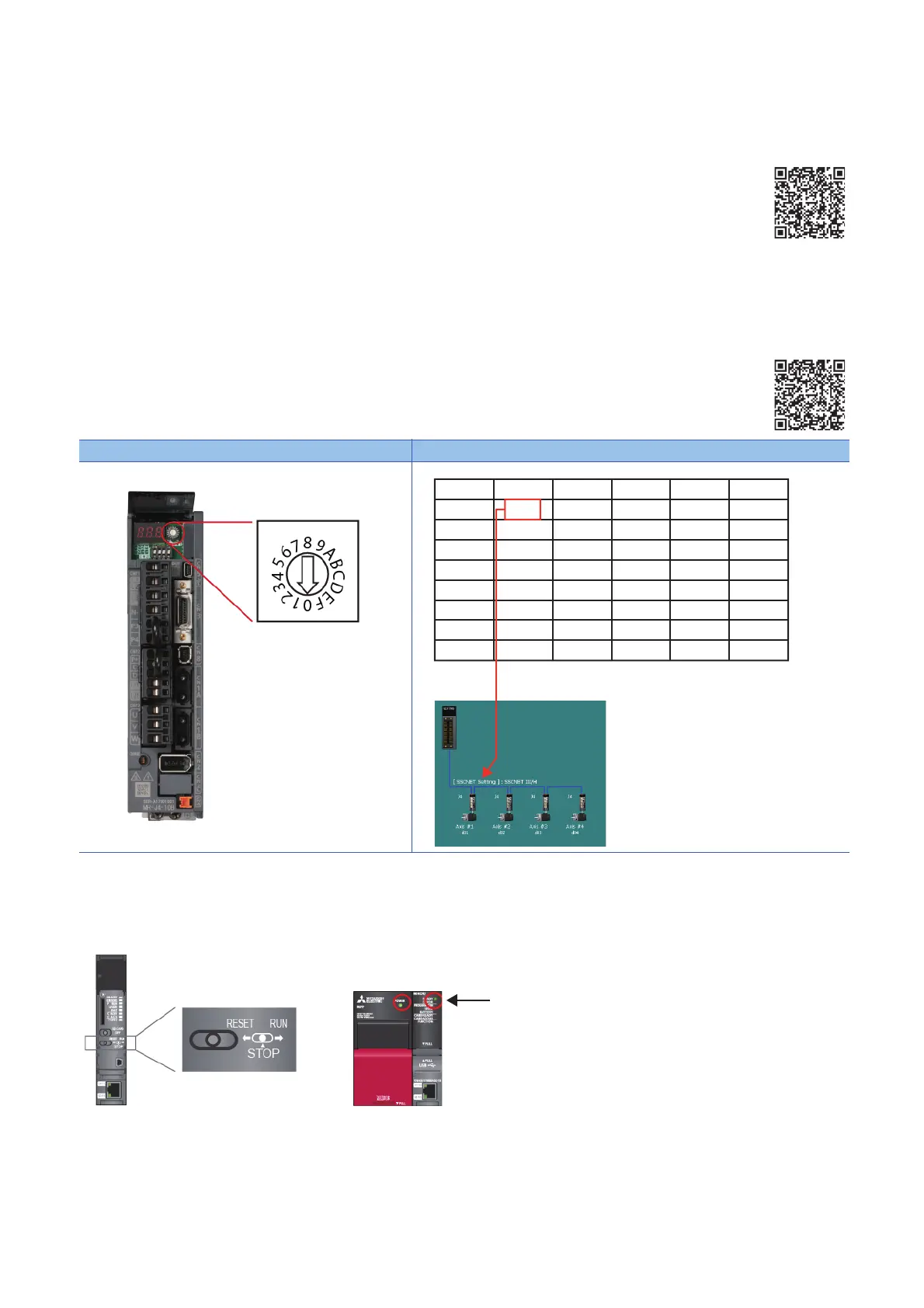
4. Axis selection rotary switch of servo amplifier
"0" to "F" of the axis selection rotary switch correspond to "d01" to "d16".
The following table shows the correspondence between SSCNET configuration and the switch No. Set the switch correctly
checking the correspondence.
5. Power-on of the system
1. Check the wiring for the power supply module.
2. Confirm that the PLC CPU is in STOP status.
3. Turn ON the power of PLC CPU.
(a) Power supply module: LED (green light) turns ON.
(b) CPU module: READY LED (green light) turns ON.
• When parameters and programs are not written to the CPU module, the ERROR LED (red light) of the PLC CPU flickers,
but no immediate error is occurring.After writing parameters and programs and turning the power OFF to ON, the ERROR
LED will be OFF.
Servo amplifier MR-J4-10B Description
View video:
View video:
Axis selection
rotary switch
SSCNET
configuration
No.
“0”
“1”
“2”
“3”
“4”
“5”
“6”
“7”
No.
“8”
“9”
“A”
“B”
“C”
“D”
“E”
“F”
dno.
d01
d02
d03
d04
d05
d06
d07
d08
dno.
d08
d09
d10
d11
d12
d13
d14
d15
Axis No.
Axis 1
Axis 2
Axis 3
Axis 4
−
−
−
−
Axis No.
−
−
−
−
−
−
−
−

 Loading...


