4 SYNCHRONOUS CONTROL STARTUP
4.3 Parameter Creation for Synchronous Control
59
4
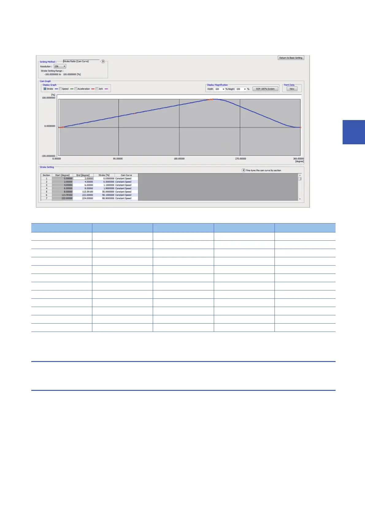
2. Cam curve creation
A cam data graph can be generated by inputting the end point and the stroke.
[Cam data]
3. Cam data creation is completed.
4.3.6 Saving a project
Refer to Section 3.3 "(6) Saving a project".
4.3.7 Writing to the Simple Motion module
Refer to Section 3.3 "(7) Writing to the Simple Motion module".
Section No. Start point[degree] End point[degree] Stroke[%] Cam curve
1 0.00000 1.60000 0.0929926 Constant speed
2 1.60000 3.20000 0.3628677 Constant speed
3 3.20000 4.80000 0.7832080 Constant speed
4 4.80000 6.40000 1.3128677 Constant speed
5 6.40000 8.00000 1.9000000 Constant speed
6 8.00000 228.47400 98.1000000 Constant speed
7 228.47400 230.07400 98.6871323 Constant speed
8 230.07400 231.67400 99.2167920 Constant speed
9 231.67400 233.27400 99.6371323 Constant speed
10 233.27400 234.87400 99.9070074 Constant speed
11 234.87400 236.47400 100.0000000 Constant speed
12 236.47400 0.00000 0.0000000 Dist. Constant speed

 Loading...


