146
6 INSTALLATION AND WIRING
6.9 Wiring of I/O Module and External Device
Wiring of sensor connector (e-CON)
Applicable connector
Prepare sensor connectors (e-CON) separately.
The following table lists reference products of connectors.
Signal name and wiring
For the signal names of the terminal block and wiring of the external device, refer to the specifications of each module. (
Page 22 Performance Specifications)
Incorrect wiring can cause malfunction of or damage on the module.
Wiring method
For how to wire the sensor connectors (e-CON), refer to the catalogs of each manufacturer.
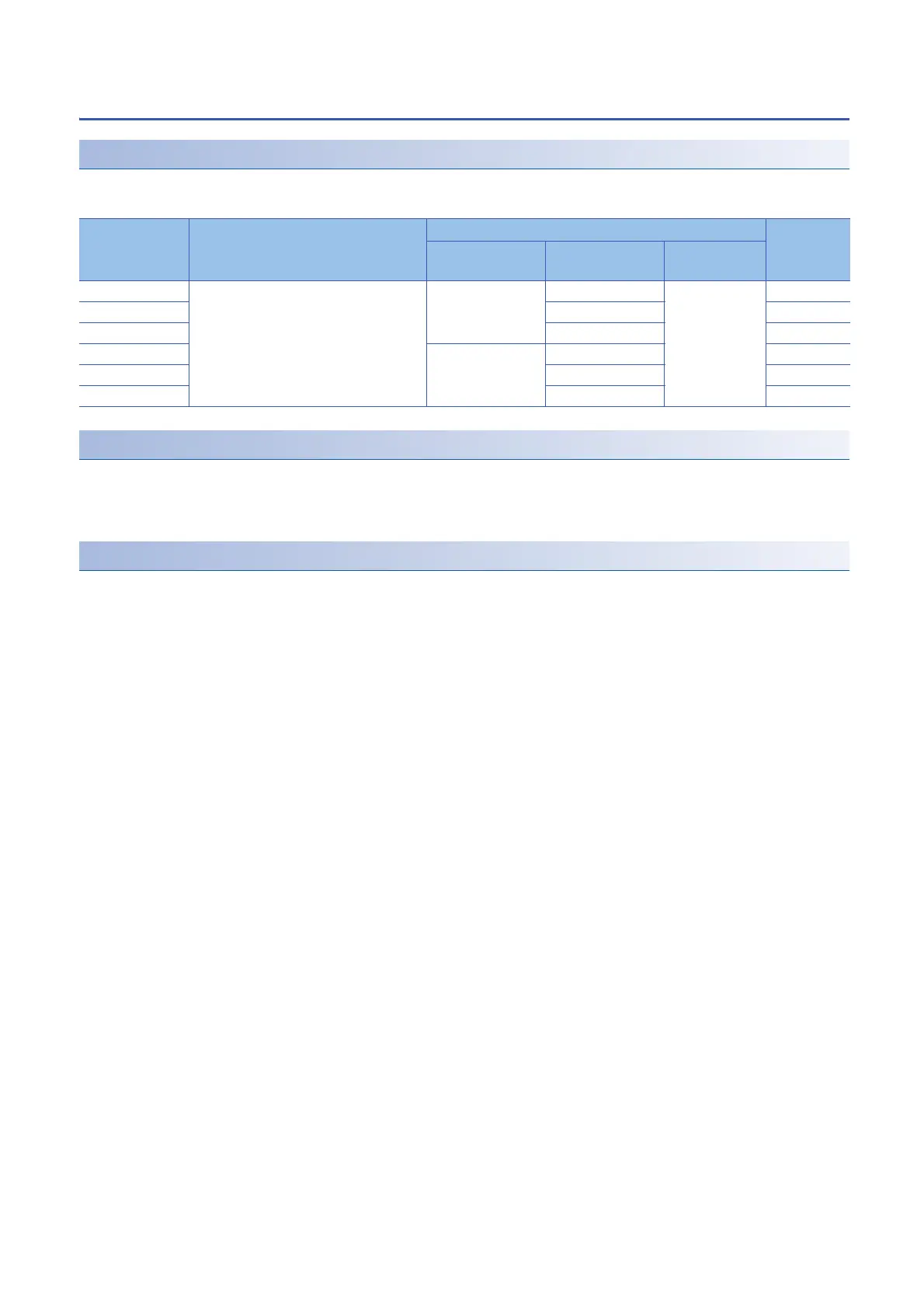
Model Manufacturer Specifications Color of the
cover
Applicable cable
(core wire size)
Applicable cable
(outer diameter)
Maximum
rated current
ECN-M014R Mitsubishi Electric System & Service Co., Ltd. 0.14 to 0.30
(26 to 24 AWG)
0.8 to 1.0mm 2.0A Red
ECN-M024Y 1.0 to 1.2mm Yellow
ECN-M034OR 1.2 to 1.6mm Orange
ECN-M044GN 0.30 to 0.50
(22 to 20 AWG)
1.0 to 1.2mm Green
ECN-M054BL 1.2 to 1.6mm Blue
ECN-M064GY 1.6 to 2.0mm Gray
 Loading...