α
2 Simple Application Controllers
Key, System Bit and Function Block Lists 14
ENG-90
*1 Number of bytes used = 19 + 1 × (Characters in equation)
*2 Number of bytes used = 8 + 4 × (Number of time switches)
*3 Number of bytes used is decided by the displayed item.
*4 Number of bytes used = 30 + 1 × (Characters in equation)
*5 Number of bytes used = 12 + 1 × (Characters in E-Mail address)
*6 Number of bytes used = 32 + 3 × (Number of screen)
*7 Number of bytes used = 37 + (Number of characters of setup commands)
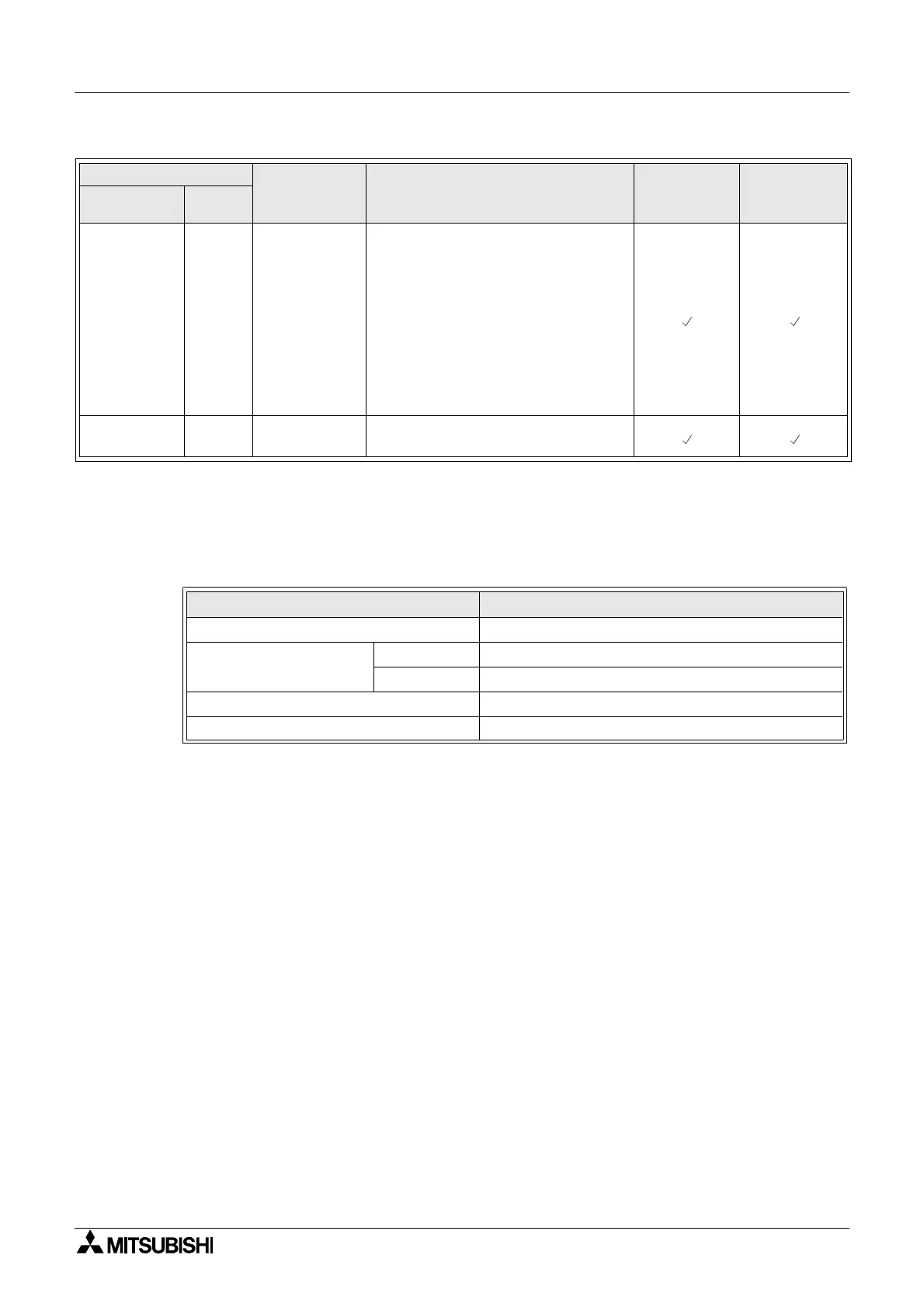
Connect _B 10
This CONNECT function block is an
internal FB used to show the memory
used by the system bits, the bits for
AS-interface, and the operation keys.
No function block appears on screen
or shows as being used in the
“Memory Configuration Usage”
dialog box, the purpose is only to
calculate the memory that is used by
the bits listed above.
System
Outputs
Out 10
Control external device through
relays and transistors.
Table 14.5:Displayed Item and number of bytes used
Displayed Item
Number of bytes, α2 Series
Characters 16 + 1
× (Each character displayed)
Analog, FB value
Value 17
Graph 23
Time, Date 14
Time Switch 17
Table 14.4: Function Block Lists
Function Block Memory
Consumption
(Byte)
Description AL2-10MR-*
AL2-14MR-*
AL2-24MR-*
Name Symbol

 Loading...


