15-24
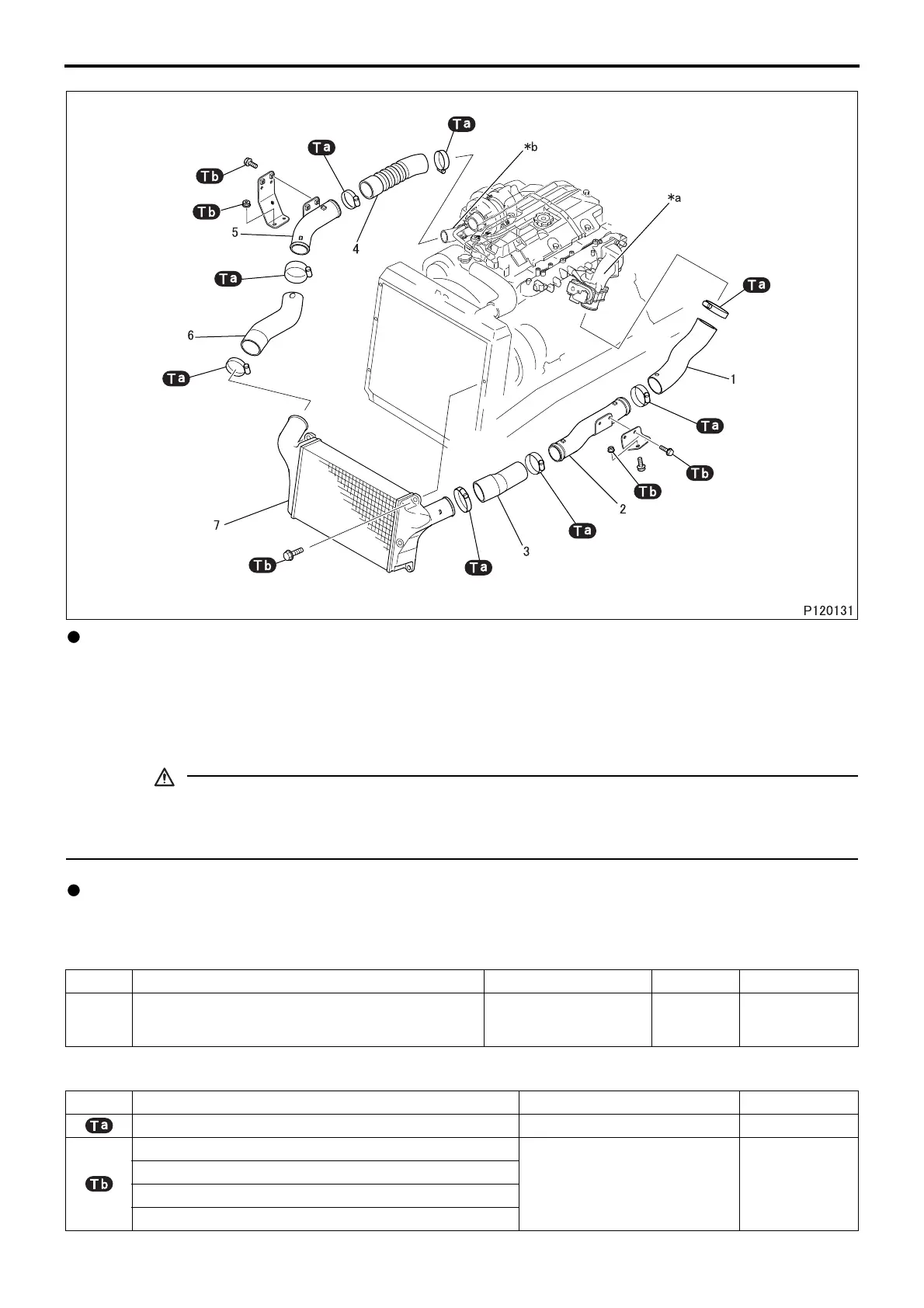
Disassembly sequence
• Do not remove forcedly the air inlet hose using a screwdriver or other similar tool. Doing so could dam-
age the fluorine treatment layer on the inside surface of the hose, deteriorating the resistance to oil of the
hose.
Assembly sequence
Follow the disassembly sequence in reverse.
Service standards
Tightening torque (Unit: N·m {kgf·m})
Location Maintenance item Standard value Limit Remedy
8
Intercooler air leakage
(air pressure: 200 kPa {2.0 kgf/cm
2
}
maintained for 30 seconds)
0 cm
3
{0 mL} – Replace
Mark Parts to be tightened Tightening torque Remarks
Clamp 6.0 to 6.5 {0.6 to 0.7} –
Bolt (bracket mounting)
12 to 15 {1.2 to 1.5} –
Nut (bracket mounting)
Bolt (intercooler mounting)
Bolt (air inlet pipe LH)
1 Air inlet hose
2 Air inlet pipe LH
3 Air inlet hose
4 Air inlet hose
5 Air inlet pipe RH
6 Air inlet hose
7 Intercooler
*
a: Air inlet duct
*
b: Turbocharger coupler
INTERCOOLER
 Loading...
