➁
Multiplication of position data (b5, b4)
The position data HP, P(I),
P(II) and CP will be multiplied
by the value shown in the table
on the left.
Example: When the value of the set position P(I)
(BFMs #18 and #17) is 123 and the BFM
#3 (b5, b4) is (1, 1), the actual position (or
travel) becomes as follows:
Motor system of units
123 × 10
3
= 123,000 (pulses)
Machine system of units
123 × 10
3
= 123,000
(µm,mdeg,10
-4
inch)
= 123
(mm,deg,10
-1
inch)
Combined system of units
➂
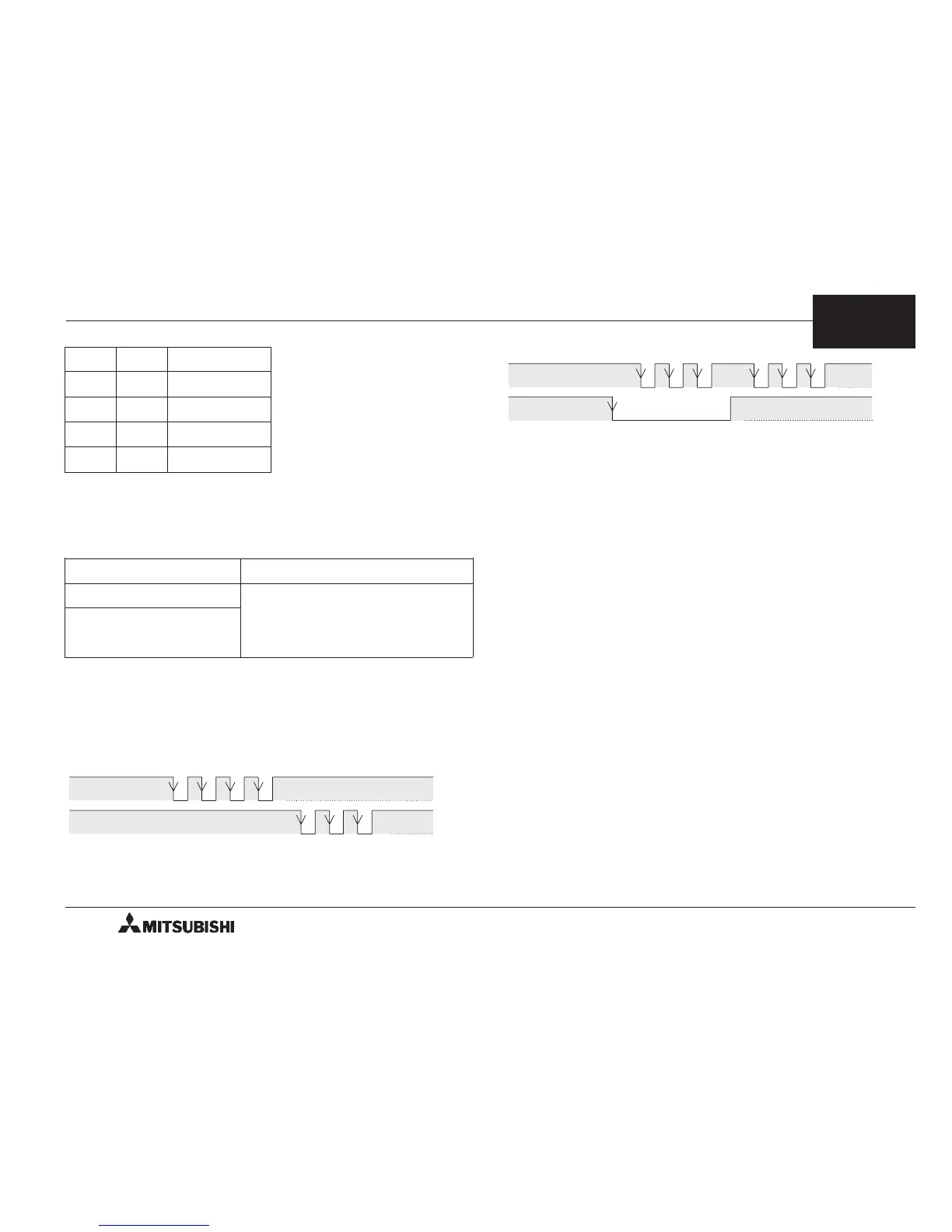
Pulse output format (b8)
The pulse output terminals FP and RP of the PGU
change as follows in accordance with the setting (0 or
1) of b8.
• When b8 = 0: Forward pulse (FP) and reverse pulse
(RP)
• When b8 = 1: Pulse (PLS) with
direction (DIR)
➃
Rotation direction (b9)
• When b9 = 0: The current position (CP) value
increases with a forward pulse (FP).
• When b9 = 1: The current position (CP) value
decreases with a forward pulse (FP).
This bit is used for the initial setting. The rotation
direction is not required to be changed in every
actual operation.
➄
Home position return direction (b10)
• When b10 = 0: The current position (CP) value
decreases during return to the
home position.
• When b10 = 1: The current position (CP) value
increases during return to the home
position.
➅
DOG input polarity (b12)
• When b12 = 0: The DOG (near point signal) input is
turned on when the workpiece is
coming near the home position.
• When b12 = 1: The DOG (near point signal) input is
turned off when the workpiece is
coming near the home position.
b5 b4 Multiplication
00 10
0
01 10
1
10 10
2
11 10
3
FP
RP
Forward pulse
Reverse pulse
OFF
ON
OFF
ON
FP (PLS)
RP (DIR) Forward Reverse
 Loading...