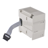
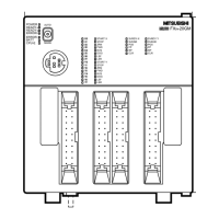
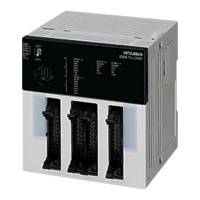
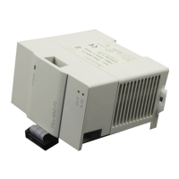
FX2N Series Programmable Controllers
xiv
Table of Contents
Guidelines of Safety................................. ii
1. Introduction ......................................1-1
1.1 Unit Accessories.................................... 1-9
1.2 World Specification................................ 1-9
1.3 Model name......................................... 1-10
1.4 Serial number ...................................... 1-11
1.5 Configuration ....................................... 1-12
1.5.1 Rules ............................................... 1-14
2. Terminal layouts...............................2-1
2.1 Relay out, 24V DC input MPU’s - Main
Processing Unit (base units).................. 2-2
2.2 Transistor output, MPU’s -
(base units)............................................ 2-3
2.3 Powered extension units ....................... 2-4
2.4 Extension blocks.................................... 2-4
2.5 FX0N Extension blocks ......................... 2-5
2.6 AC 110V Input, MPUs - (base units) ..... 2-6
3. Installation........................................3-1
3.1 Product outline....................................... 3-2
3.2 RUN/STOP Control ............................... 3-4
3.3 General specifications ........................... 3-6
3.4 PLC mounting arrangements................. 3-8
3.5 DIN rail mounting................................. 3-11
3.6 Direct mounting ................................... 3-12
3.7 General notes ...................................... 3-13
3.8 Extension Board Installation................ 3-14
3.9 Extension Units/Blocks Installation...... 3-16
4. Wiring techniques.............................4-1
4.1 Wiring cautions...................................... 4-1
4.2 Termination at screw terminals.............. 4-4
4.3 Power supply......................................... 4-9
4.4 Earthing/Grounding ............................. 4-15
4.5 Service power supply .......................... 4-16
5. Inputs ...............................................5-1
5.1 24V DC input specifications................... 5-1
5.1.1 Typical wiring..................................... 5-2
5.1.2 Input circuit connection...................... 5-3
5.1.3 Diodes and inputs connected in
series................................................. 5-4
5.1.4 Resistors and inputs connected in
parallel............................................... 5-5
5.2 AC 110V Input, MPUs ........................... 5-6
5.2.1 110V AC input specifications............. 5-7
5.2.2 Typical wiring..................................... 5-8
5.2.3 Programming caution ........................ 5-9
6. Outputs............................................ 6-1
6.1 Relay output specification...................... 6-1
6.1.1 Product life of relay contacts..............6-3
6.1.2 Relay output example........................6-8
6.1.3 Output circuit configuration................6-9
6.1.3 Configuration du circuit de sortie .......6-9
6.2 Triac (SSR) output specifications ........ 6-12
6.2.1 In-rush currents................................6-14
6.2.2 Triac output example .......................6-15
6.2 Output circuit configuration.................. 6-16
6.3 Transistor output specification............. 6-18
6.3.1 Response times...............................6-20
6.3.2 Transistor output example ...............6-21
6.4 Applying safe loads.............................. 6-22
7. Diagnostics...................................... 7-1
7.1 Preliminary checks................................. 7-1
7.2 Basic diagnostics................................... 7-2
7.2.1 Power ON, PLC OFF.........................7-2
7.2.2 BATT.V LED ON................................7-4
7.2.3 PROG.E LED flashes ........................7-6
7.2.4 CPU.E LED ON .................................7-7
7.3 Common errors.................................... 7-10
7.4 Replacing the battery........................... 7-11
7.5 Maintenance ........................................ 7-13
7.6 Error flags ON indicates error.............. 7-14
7.7 Error registers...................................... 7-16
7.8 Error codes .......................................... 7-18
7.9 Instruction list....................................... 7-19
Appendix A: Associated Manuals......... A-1
Appendix B: Discontinued models ....... B-1
Appendix C: Index................................C-1
ENG
FX2N Series Programmable Controllers

 Loading...


