3-69 Parallel I/O interface
3 Controller
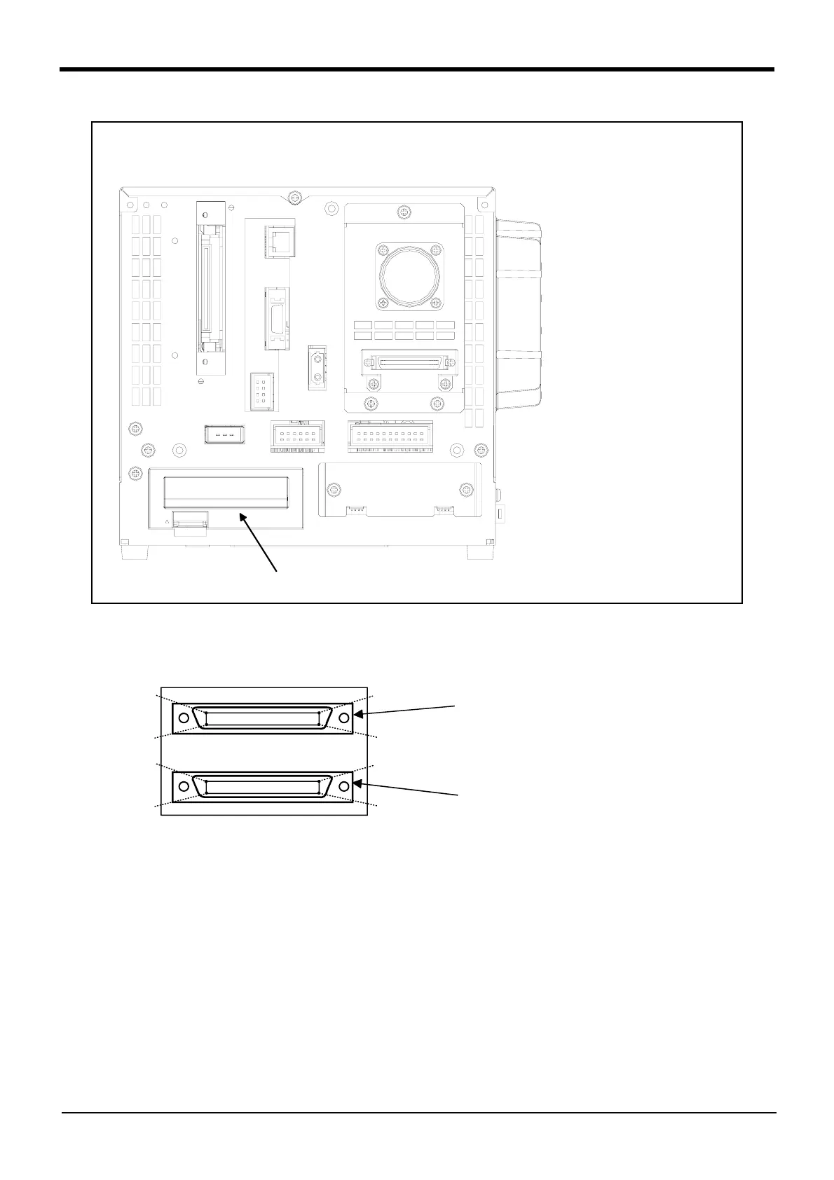
Fig.3-23 : Parallel I/O interface installation position (CR1DA-700 series)
■ Pin layout of connector
Fig.3-24 : Pin layout of connector
<CR1DA-700 series>
SLOT1
コントローラ背面
Controller rear
* The figure isstandard specification.
(CE marking specification is the same.)
1B
1A
20A
20B
1D
1C
20C
20D
Connector<2>
Output 16 to 31
Input 16 to 31
(when station number 0)
Connector<1>
Output 0 to 15
Input 0 to 15
(when station number 0)
 Loading...


