6.
.HQ,W.TQ
USE EACH FUNCTION
.
,
;.
UELSEC-A
[Explanation]
(1)
Monitoring by designating
1
point
(a) The ON/OFF states of bit devices
(X,
Y,
M,
L,
S,
6)
can
be
monitored.
Monitoring of an
off
line switch state can be also executed. (There is
no offline switch function in the AOJ2CPU, A2ACPU, A3HCPU,
1
A3MCPU and A3ACPU.)
*
An offline switch,is dlsplayed by using
the
Help operation or offline
switch setting of Me TEST Mode. (See Sections
6.6.5
and
6.7.5.)
(b) The current values of word devices
(D,
W,
R)
can be monitored.
(c) The set values, current values, and ON/OFF states of contact timer
counters (T,
C)
can be monitored.
However, when the set value is set at
a
word device, a device number
is displayed.
P
f
However, only
4
points of a bit device, timer/counter, or word device
n
,
can be monitored.
'b
*
Monitoring cannot be executed by mixing bit devices, timers, count-
ers, and word devices.
(d) The number of monitored points is
4
max.
I
I
(2) Monitoring by designating multiple points
\
I
e
(a) Designation of multiple bit devices
Monitoring the ON/OFF state of bit devices is executed in units of
8
points.
When a set bit device number cannot be divided by
8,
it is monitored
automatically by device number in
units
of
8
points. For example,
if
multiple
M10
are designated,
M8
fo
M15
are monitored.
These are handled as 32-bit data, and a current values are moni-
I
tored.
However, only
4
points
of
a bit device or word device can be
monitored.
Monitoring cannot be executed by mixing bit devices and word
devices.
(b)
Designatiba
qf
multiple word devices
(c) The number of points to be monitored is
4
max.
1
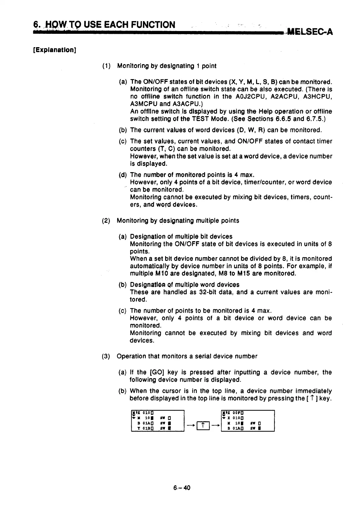
(3) Operation that monitors a serial device number
(a)
If
the
[GO]
key is pressed after inputting a device number, the
4
following device number is displayed.
(b) When the cursor
is
in the top line, a device number immediately
before displayed in the top line is monitored by pressing the
[
t
]
key.
1
i
*
!
Mh
OOrO
v
-1
0100
6.-
40
I
I
0

 Loading...


