SW1
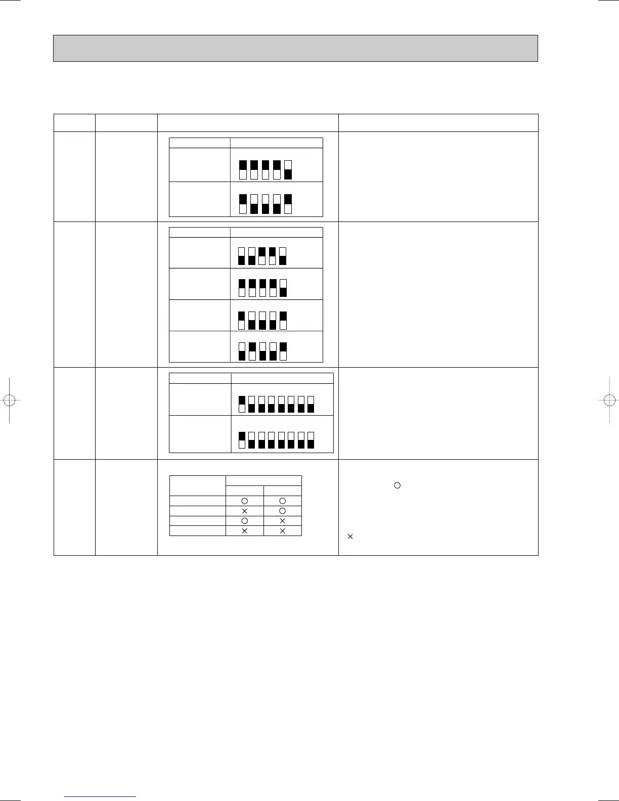
Setting by the dip switch and jumper wire
Functions
Jumper wire
Model
settings
SW5
System
settings
Capacity
settings
Pair number
setting with
wireless
remote
controller
Remarks
SW2
J41
J42
0
1
2
3 ~ 9
Wireless remote
controller setting
Control PCB setting
J41 J42
<Settings at time of factory shipment>
Wireless remote controller: 0
Control PCB: (for both J41 and J42)
Four pair number settings are supported.
The pair number settings of the wireless remote
controller and indoor control PCB (J41/J42) are
given in the table on the left.
(' ' in the table indicates the jumper line is disco-
nnected.)
SW5-3 Main/Sub setting
OFF : Main ON : Sub
SW5-4 Rotaion operation setting
OFF : Not avairable ON : avairable
MODELS SW1
MODELS SW5
MODELS SW2
1 2 3 4 5
ON
OFF
PLH-AAK
1 2 3 4 5
ON
OFF
PL
H
-3AA
K
PL
H
-3AA
K
H
PL
H
-4AA
K
PL
H
-4AA
K
H
PL
H
-5AA
K
PL
H
-5AA
K
H
PL
H
-6AA
K
PL
H
-6AA
K
H
1 2 3 4 5
ON
OFF
1 2 3 4 5
ON
OFF
1 2 3 4 5
ON
OFF
1 2 3 4 5
ON
OFF
PLH-AAKH
12345678
12345678
ON
OFF
PLH-AAK
ON
OFF
PLH-AAKH
8-8. FUNCTIONS OF DIP SWITCH AND JUMPER WIRE
Each function is controlled by the dip switch and the jumper wire on control p.c. board.
 Loading...