50
9
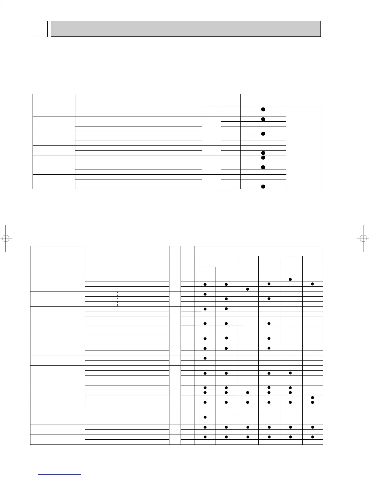
FUNCTION SETTING
Function Settings
No.
Mode
No.
Setting
Initial setting
(
Factory setting
)
- : Not available
4-Way cassette
Ceiling
concealed
Ceiling
suspended
Wall
mounted
Floor
standing
PLH-AAK(H)
PEH-EAK(H)
PCH-GAK(H)
PKHGAKL(H)
PSH-GAK(H)
PEHD-EAK(H)
PKA-FAKL(H)
Filter sign 100Hr 1
2500Hr 07 2
No filter sign indicator
3
Air flow Quiet Standard 1 - - -
(
Fan speed
)
Standard
High ceiling1
08 2 - - -
High ceiling
High ceiling2
3---
No.of air outlets 4 directions 1 - - - -
3 directions 09 2 - - - -
2 directions
3-----
Optional high efficiency
Not supported
10
1
---
filter Supported
2
---
Vane setting
No vanes
(
Vane No.3 setting:PLH-AAK(H)only
)
1---
Vane No.1 setting
11 2 - - -
Vane No.2 setting
3---
Energy saving air Disabled
12
1
---
flow
(
Heating mode
)
Enabled
2
---
Optional humidifier Not supported
13
1
--- -
(
PLH-AAK(H) only
)
Supported
2
--- -
Vane differential setting No.1 setting
(
TH2: 24-28:
)
1- -
in heating mode No.2 setting
(
Standard
,
TH2:28-32:
)
14 2 - -
(
cold wind prevention
)
No.3 setting
(
TH2: 32-38:
)
3- -
Swing Not available
23
1
--
Available
2
--
Set temperature in heating Available
24
1
mode
(
4 deg up
)
Not available
2
Fan speed when the Extra low 1
heating thermostat is OFF
Stop
25 2
Set fan speed
3
Quiet operation mode Disabled
(
Standard
)
26
1
--- -
of PLH-AAK(H)
(
Fan speed
)
Enabled
(
Quiet operation mode
)
2
--- -
Fan speed when the
Set fan speed
27
1
cooling thermostat is OFF Stop
2
Detection of abnormality of Available
28
1
the pipe temperature
(
P8
)
Not available
2
}
PLH-AAK(H)
PLH-KAK(H)
-
-
-
-
Function
Settings
Mode No.
Setting No.
Initial setting
(when sent from the factory)
Remarks
Power failure
automatic recovery
Indoor temperature
detecting
LOSSNAY
connectivity
Power supply
voltage
Frost prevention
temperature
Humidifier control
Rotation
OFF
ON
Indoor unit's (Main) internal sensor
Remote controller's internal sensor
Not supported
Supported (indoor unit not equipped with outdoor air intake)
Supported (indoor unit equipped with outdoor air intake)
240V
220V,230V
1: (Normal)
-3:
When the compressor operates, the humidifier also operates.
When the fan operates, the humidifier also operates.
24h cycle
168cycle
Back up function
1
2
1
2
3
1
2
3
1
2
1
2
1
2
1
2
3
01
02
03
04
15
16
20
The setting is
applied to all
the units in the
same
refrigerant
system.
9-1. UNIT FUNCTION SETTING BY THE REMOTE CONTROLLER
Each function can be set according to necessity using the remote controller. The setting of function for each unit can only be
done by the remote controller. Select function available from the table 1.
<Table 1> Function selections
(1) Functions available when setting the unit number to 00 (Select 00 referring to 4 setting the indoor unit number.)
W1 The functions below are available only when the wired remote controller is used.The functions are not available for floor
standing models.
(2) Functions available when setting the unit number to 01-03 or AL (07 in case of wireless remote controller)
• When setting functions for an indoor unit in an independent system, set the unit number to 01 referring to 4 setting the
indoor unit number.
• When setting functions for a simultaneous- Twin Triple indoor unit system, set the unit number to 01 to 03 for each indoor
unit in case of selecting different functions for each unit referring to 4 setting the indoor unit number.
• When setting the same functions for an entire simultaneous Twin Triple-indoor unit system, set refrigerant address to AL
(07 in case of wireless remote controller) referring to 4 setting the indoor unit number.
OC360--2.qxp 06.2.24 1:55 PM Page 50
 Loading...