1 Overview
2
No. 99MBC109B
1.3
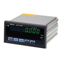
Part Names and Functions
1.3.1 Front Side of the Main Body
EH-102P/EH-102Z/EH-102S/EH-102D
(2-axis model)
EH-101P
(1-axis model)
①
②
③ ④ ⑤
⑥
⑦
⑧
⑨ ⑩ ⑪ ⑫ ⑬ ⑭
①
③
⑤
⑦
⑧
⑨ ⑩ ⑪ ⑫ ⑬
Symbol
Name Description
①
Tolerance judgment
indicator A
Indicates the tolerance judgment result of
the Linear Gage (INPUT A) connected to
the Linear Gage input connector A by color.
②
Tolerance judgment
indicator B
Indicates the tolerance judgment result of
the Linear Gage (INPUT B) connected to
the Linear Gage input connector B by color.
③
Display A Displays the counter value from INPUT A.
④
Display B Displays the counter value from INPUT B.
⑤
Peak mode indicator Indicates the Peak-mode type.
⑥
BANK indicator Indicates the currently selected BANK
number. For details about BANK, see
"4.2 Switching the Displayed BANK (2-
Axis Models Only)" (page 25).
⑦
Total Judgment indicator Indicates the result of the total tolerance
judgment by color.
 Loading...