4.2
ASSIGNMENTS AND SETTINGS
FOR
SWITCHES
SW1
THROUGH SW8
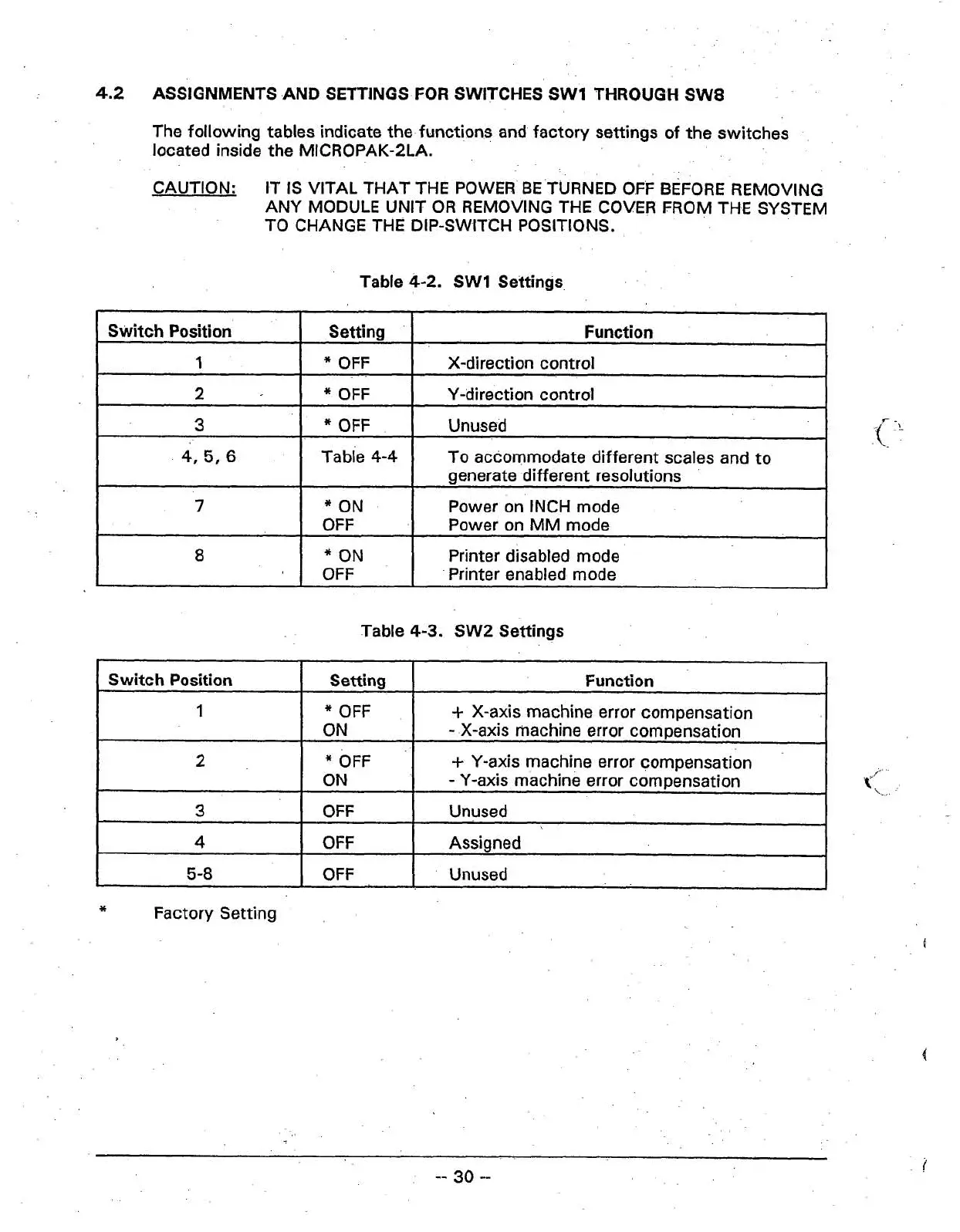
The following tables indicate the functions and factory settings of the switches
located inside the MICROPAK-2LA.
CAUTION:
IT IS VITAL THAT THE POWER BE TURNED OFF BEFORE REMOVING
ANY MODULE UNIT OR REMOVING THE COVER FROM THE SYSTEM
TO CHANGE THE DIP-SWITCH POSITIONS.
Table
4-2.
SW1
Settings
Table 4-3. SW2 Settings
Switch Position
1
2
3
4,
5,
6
7
8
A
Switch Position
I
Setting
I
Function
I
I
Setting
*
OFF
*
OFF
*
OFF
Table
4-4
*
ON
OFF
*
ON
OFF
-
Function
X-direction control
Y-direction control
Unused
To accommodate different scales and to
generate different resolutions
Power on INCH mode
Power on MM mode
Printer disabled mode
Printer enabled mode
1
I
4
I
OFF
!
Assigned
I
I
2
3
I
5-8
I
OFF
1.
Unused
. .
1
*
OFF
ON
I
Factory Setting
+
X-axis machine error compensation
-
X-axis machine error compensation
*
OFF
ON
OFF
+
Y-axis machine error compensation
-
Y-axis machine error compensation
Unused
t'
\.