OPERATION
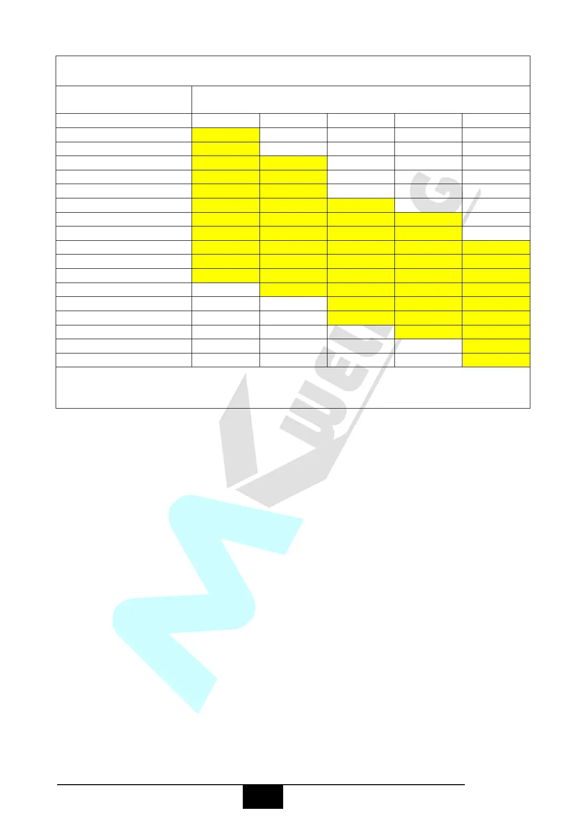
WELDING WIRE DIAMETER CHART
RECOMMENDED WIRE DIAMETERS
For material thickness of 5.0mm and greater, multi-pass runs or a beveled joint design
may be required depending on the amperage capability of your machine.
Gas selection - The purpose of the gas in the MIG process is to protect / shield the wire,
the arc and the molten weld metal from the atmosphere. Most metals when heated to a
molten state will react with the air in the atmosphere, without the protection of the shielding
gas the weld produced would contain defects like porosity, lack of fusion and slag inclusions.
Additionally some of the gas becomes ionised (electrically charged) and helps the current
flow smoothly.
The correct gas flow is also very important in protecting the welding zone from the
atmosphere. Too low flow will give inadequate coverage and result in weld defects and
unstable arc conditions. Too high flow can cause air to be drawn into the gas column and
contaminate the weld zone.
Use the correct shielding gas. Co2 is good for steel and offers good penetration
characteristics, the weld profile is narrower and slightly more raised than the weld profile
obtained from Argon Co2 mixed gas. Argon Co2 mix gas offers better weld ability for thin
metals and has a wider range of setting tolerance on the machine. Argon 80% Co2 20% is
a good all round mix suitable for most applications.


 To Next Page