Chapter Three: Overview Electrical Connections
33
P.C. Edge Card Connector
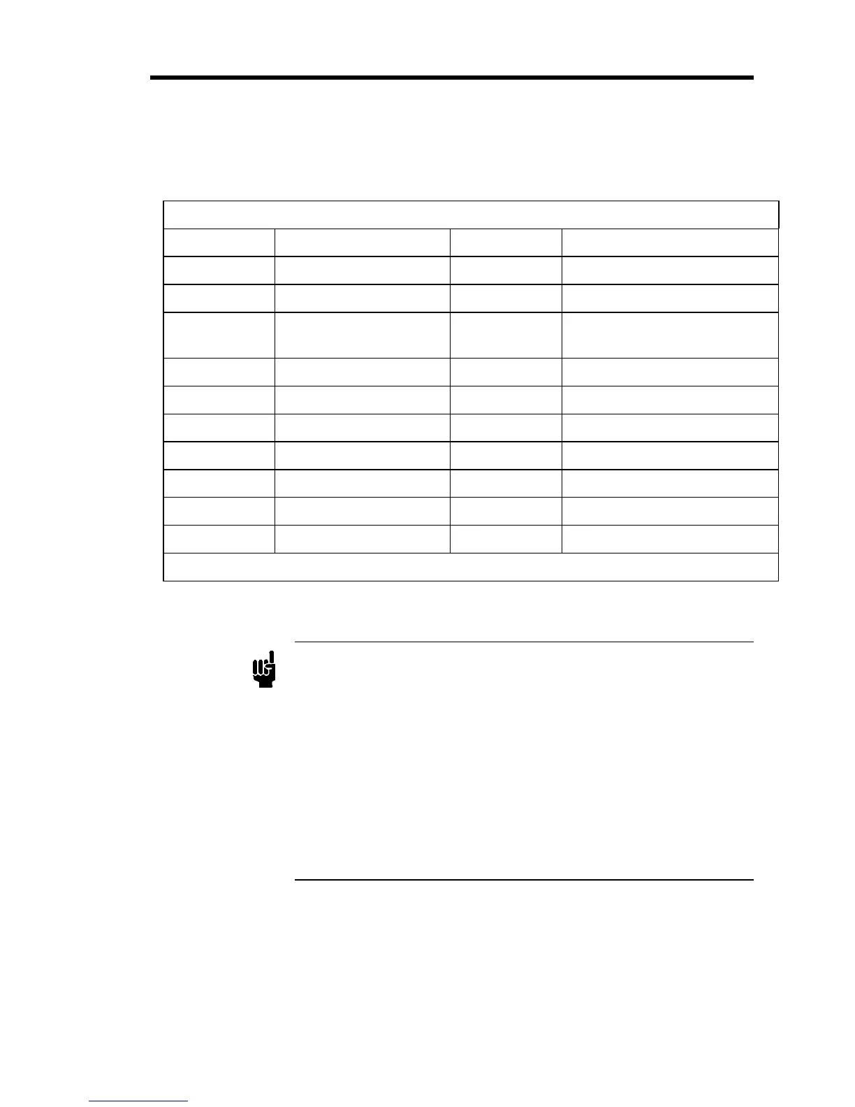
Table 7 shows the pinout of the 20-pin Edge Card connector for a mass flow controller.
20-Pin Edge Card Connector Pinout
Pin Number Function Pin Number Function
1 Chassis Ground A Set Point Input (0 to +5 VDC)*
2 Power Supply Common B Signal Common
3 Flow Output
(0 to +5 VDC)
C Signal Common
4 +15 VDC D Valve Open (TTL low)*
5 Optional Input* E No Connection
6 No Connection F -15 VDC
7 Key H Key
8 No Connection J MKS Test Point*
9 No Connection K No Connection
10 Signal Common L Valve Close (TTL low)*
* For an MFC only, No Connection for an MFM
Table 7: 20-Pin Edge Card Connector Pinout
Note
1. The “No Connection” pin assignment refers to a pin with no internal
connection.
2. Pins 1 through 10 are located on one side of the gold finger
connection and pins A through L are located on the opposite side of
the gold finger connection.
3. The 0 to 5 VDC flow signal output comes from pin 3 and is
referenced to pin B (signal ground).
4. Any appropriate 0 to 5 VDC input signal of less than 20K ohm
source impedance referenced to pin B can be used to supply a set
point signal to pin A.

 Loading...


