24
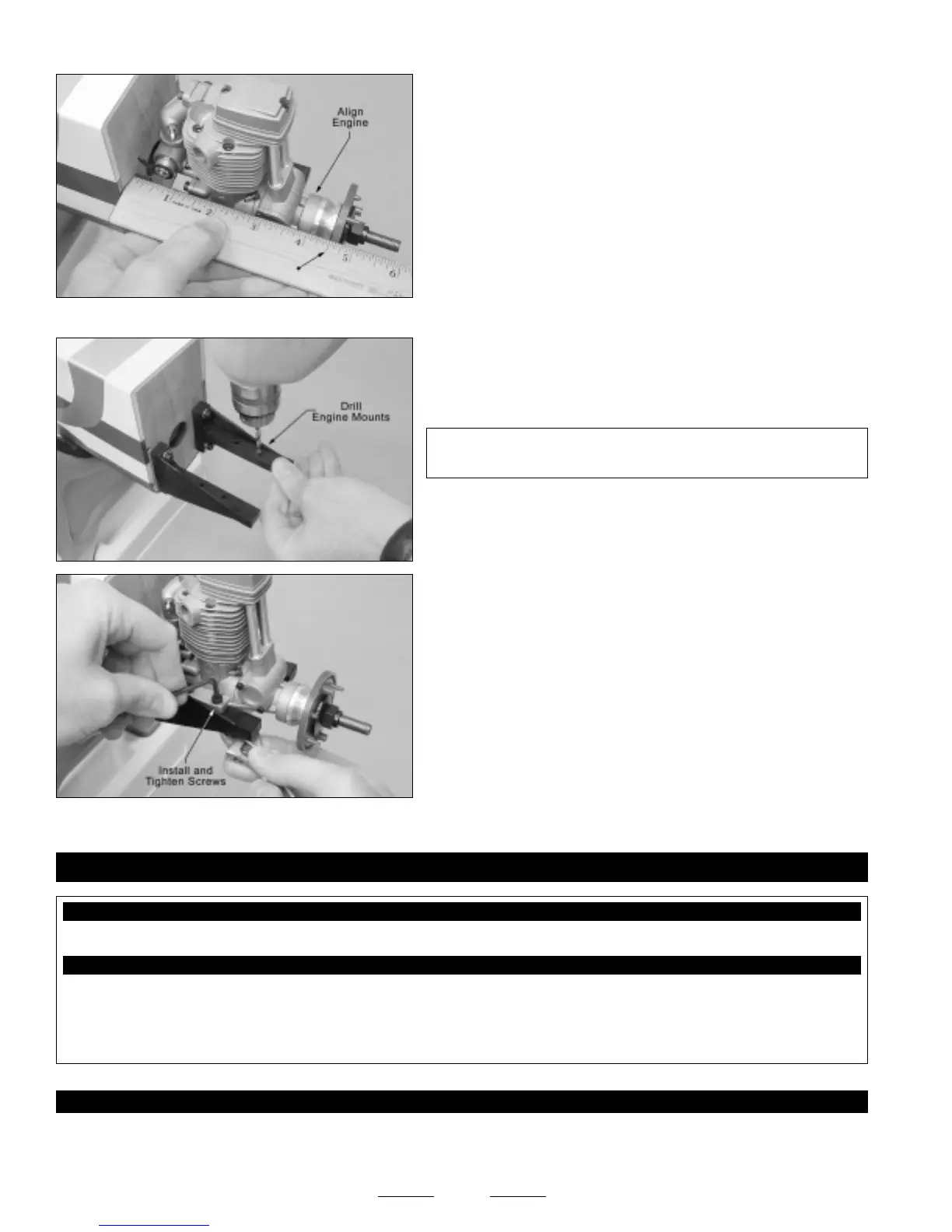
❑ With the fuselage upside down, set the engine onto the engine
mounting beams.
❑ Using a ruler, measure the distance from the firewall to the back of
the spinner backplate. Adjust the depth of the engine so that the
measurement is 4-1/2".
❑ Using a pencil, carefully mark the locations of the engine mounting holes onto the engine mounting beams.
❑ Remove the engine and drill 3/32" diameter pilot holes through the
engine mounting beams at the marks you drew.
✦✦
✦✦
✦IMPORTANT
✦✦
✦✦
✦ Be careful that you drill the holes straight down
and not at an angle.
❑ Carefully enlarge the 3/32" diameter pilot holes, using a 5/32"
diameter drill bit.
❑ Install the engine using four M4 x 25mm socket-cap screws, eight
M4 flat washers and four M4 lock nuts.
☞
Tighten the screws and lock nuts firmly to hold the engine securely
into place.
❑ Kwik Bond Thin C/A
❑ # 1 & # 2 Phillips Head Screwdrivers
❑ Wire Cutters
❑ Needle Nose Pliers
❑ Electric Drill
❑ 1/16" & 5/64" Drill Bits
❑ Ernst Airplane Stand
❑ Ruler
YOU'LL NEED THE FOLLOWING PARTS FROM THE KIT:
YOU'LL NEED THE FOLLOWING TOOLS AND SUPPLIES:
SECTION 13: THROTTLE CONTROL SYSTEM INSTALLATION
❑ (1) 13-1/4" Plain Wire w/Z-Bend
❑ (1) Adjustable Pushrod Connector w/Machine Screw & Nut
STEP 1: INSTALLING THE THROTTLE SERVO
❑ Install the rubber grommets and brass collets onto your throttle servo, making sure to install the collets with the flanges toward
the bottom of the servo.
Continued On Next Page
☛☛
☛☛
☛