19
STEP 3: HINGING THE RUDDER
❑ Hinge the rudder, using the same techniques that you used to hinge
the ailerons and the elevator halves. The rudder is hinged using three
hinges. When hinging the rudder, there should be a 1/16" wide gap
between the end of the stabilizer and the rudder counterbalance. There
should also not be more than a 1/32" wide hinge gap.
✦✦
✦✦
✦IMPORTANT
✦✦
✦✦
✦ After allowing the C/A to fully cure, pull on the rudder to check the integrity of the hinges. Apply more C/A to the
hinge(s) if necessary.
❑ # 1 Phillips Head Screwdriver
❑ Excel Modeling Knife
❑ Electric Drill
❑ 1/16" Drill Bit
❑ Ernst Airplane Stand
❑ Ruler
❑ Pencil
YOU'LL NEED THE FOLLOWING PARTS FROM THE KIT:
YOU'LL NEED THE FOLLOWING TOOLS AND SUPPLIES:
SECTION 10: TAIL SKID INSTALLATION
❑ (1) Prebent Tail Skid
❑ (2) Nylon Mounting Straps
❑ (4) M2 x 10mm Wood Screws
STEP 1: INSTALLING THE TAIL SKID
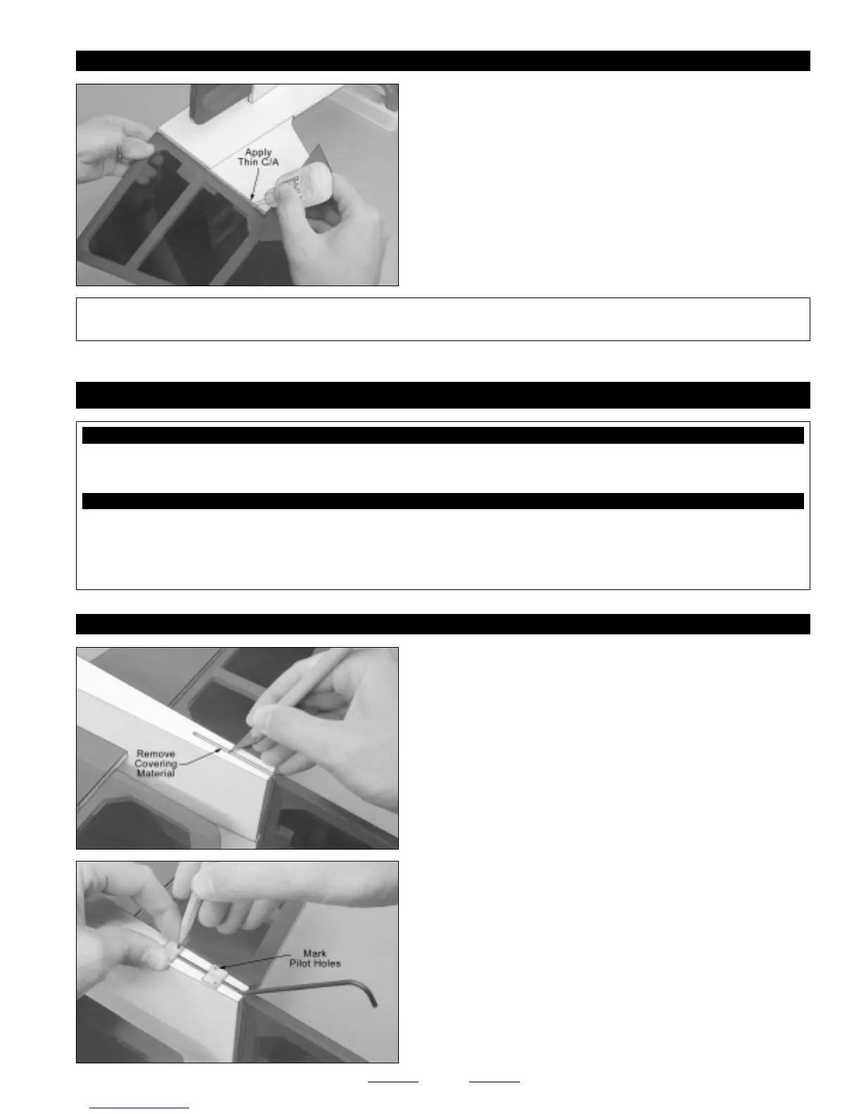
❑ Using a modeling knife, cut away and remove the covering material
from over the tail skid mounting slot in the bottom of the fuselage. The
slot is 2-1/2" long and 1/8" wide.
❑ Insert the 90º bend in the tail skid into the predrilled hole in the tail
skid mounting slot, then firmly push the tail skid down into the slot.
❑ Place the two nylon mounting straps equally spaced apart over the
tail skid and use a pencil to mark the locations of the four mounting
holes onto the bottom of the fuselage.
Continued On Next Page
☛☛
☛☛
☛