32
❑ Kwik Bond Thin C/A
❑ # 1 Phillips Head Screwdriver
❑ Wire Cutters
❑ Needle Nose Pliers
❑ Excel Modeling Knife
❑ Electric Drill
❑ 1/16" & 5/64" Drill Bits
❑ Ernst Airplane Stand
❑ Ruler
❑ Pencil
❑ Masking Tape
YOU'LL NEED THE FOLLOWING PARTS FROM THE KIT:
YOU'LL NEED THE FOLLOWING TOOLS AND SUPPLIES:
SECTION 16: RUDDER CONTROL SYSTEM INSTALLATION
❑ (2) 38-1/2" Threaded Wires w/90º Bends
❑ (2) Nylon Control Horns (w/o Backplates)
❑ (2) Nylon Clevises
❑ (2) Nylon 90º Snap-Keepers
❑ (4) M2 x 12mm Machine Screws
❑ (4) M2 Flat Washers
❑ (4) M2 Hex Nuts
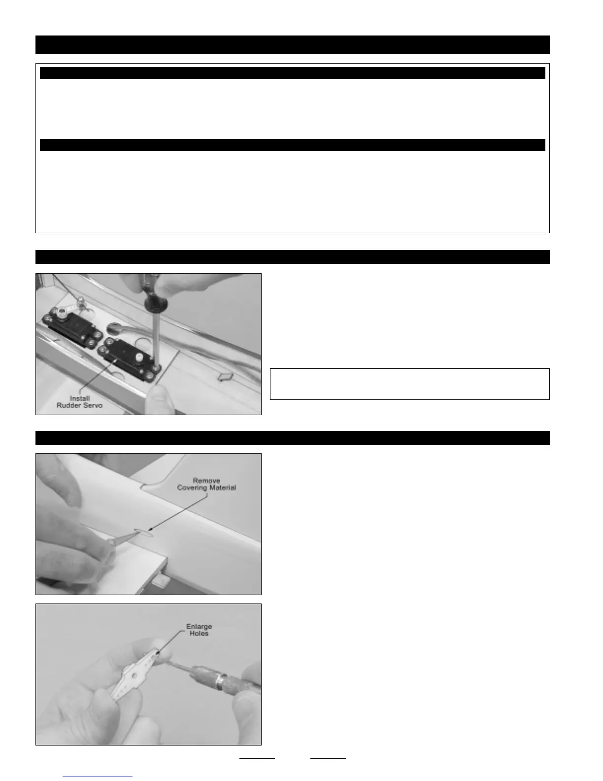
STEP 1: INSTALLING THE RUDDER SERVO
❑ Install the rubber grommets and brass collets onto your rudder servo,
making sure to install the collets with the flanges toward the bottom of
the servo.
❑ Install the rudder servo into the plywood servo tray, making sure to
drill 1/16" diameter pilot holes for the mounting screws.
✦✦
✦✦
✦IMPORTANT
✦✦
✦✦
✦ The servo output shaft should be toward the back
of the fuselage, as shown.
STEP 2: INSTALLING THE RUDDER PUSHROD ASSEMBLY
❑ Using a modeling knife, cut away and remove the covering material
from over the rudder pushrod exit hole in each side of the fuselage. The
holes are located 5-1/4" in front of the rudder hinge line and 5/8" above
the top of the horizontal stabilizer.
❑ Using a modeling knife, cut away two arms from a "4-point" servo horn.
❑ Enlarge the hole in each arm that is 9/16" out from the center of the
servo arm, using a 5/64" diameter drill bit.
Continued On Next Page
☛☛
☛☛
☛