34
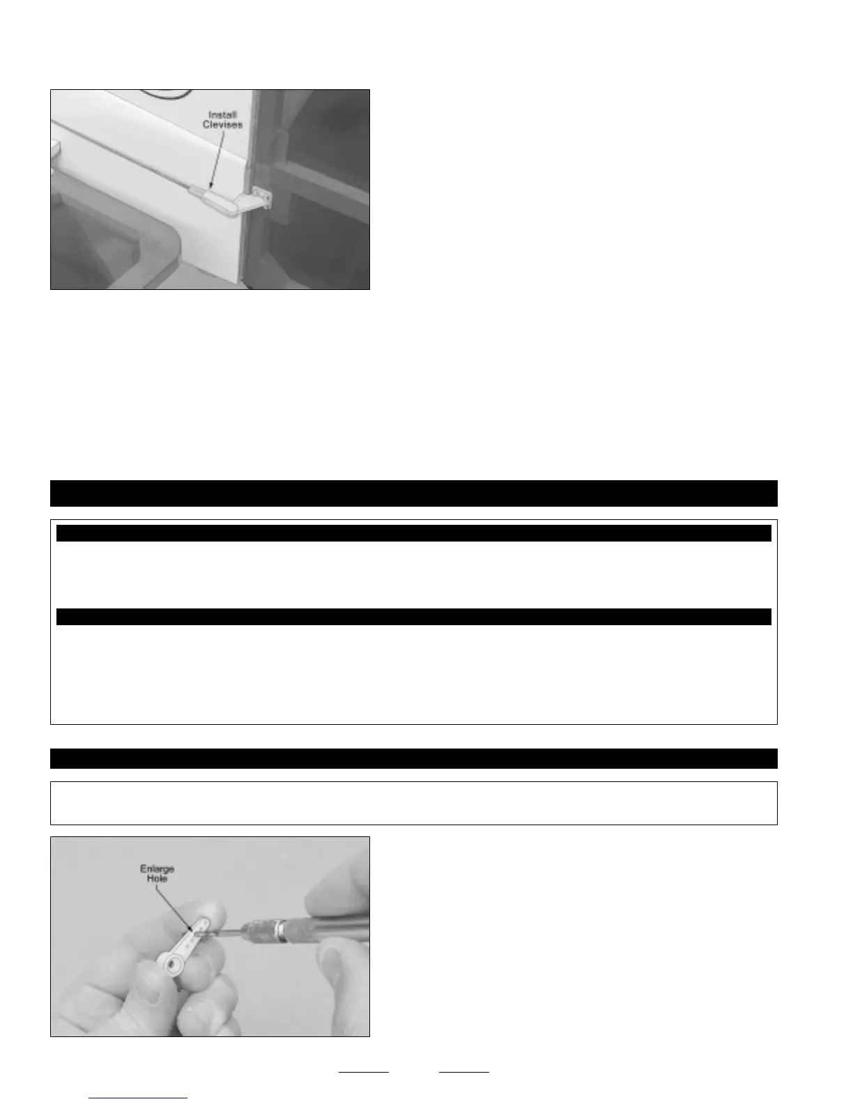
❑ Thread two nylon clevises onto the pushrod wires and snap them
into the outermost hole in the control horns.
☞
Hold the pushrod wires with a pair of pliers to prevent them from
turning or twisting when installing the clevises.
❑ Use a piece of masking tape, taped between the rudder and the stabilizer, to hold the rudder centered.
❑ Remove the masking tape from the rudder and double-check that the servo horn and the rudder are still centered. If the
rudder is not centered, adjust the clevises until it is. Move the rudder right and left several times to ensure that the linkage assembly
does not bind. It should operate smoothly in both directions.
❑ Move the rudder control stick completely to one side. Let the control stick go and check to see if the rudder returns to center. Do
this a couple of times in each direction. If the rudder does not return to center consistently, adjust the tension of the pushrod wires
by adjusting the clevises. Ideally, the pushrod wires should be as tight as possible, while still allowing the rudder to return to center.
The pushrod wires should not have slack in them, yet they should not be so tight that the linkage and/or the servo bind.
❑ Kwik Bond Thin C/A
❑ # 1 Phillips Head Screwdriver
❑ Wire Cutters
❑ Needle Nose Pliers
❑ Excel Modeling Knife
❑ Electric Drill
❑ 5/64" Drill Bit
❑ Ruler
❑ Pencil
❑ Masking Tape
YOU'LL NEED THE FOLLOWING PARTS FROM THE KIT:
YOU'LL NEED THE FOLLOWING TOOLS AND SUPPLIES:
SECTION 17: AILERON CONTROL SYSTEM INSTALLATION
❑ (2) 3-1/8" Threaded Wires w/90º Bends
❑ (2) Nylon Control Horns w/Backplates
❑ (2) Nylon Clevises
❑ (2) Nylon 90º Snap-Keepers
❑ (4) M2 x 16mm Machine Screws
STEP 1: INSTALLING THE AILERON PUSHRODS
✦✦
✦✦
✦IMPORTANT
✦✦
✦✦
✦ Before installing the control horns, please refer to section 23 on page # 41 about sealing the control surface
hinge gaps. It is strongly recommended that you do this, and it's much easier to do it now than later.
❑ Using a modeling knife, cut away all but one arm from a "4-point"
servo horn.
❑ Enlarge the hole in the servo arm that is 9/16" out from the center of
the servo arm, using a 5/64" diameter drill bit.
Continued On Next Page
☛☛
☛☛
☛