7
Continued On Next Page
☛☛
☛☛
☛
❑ (1) Plywood Wing Joiner (W34)
❑ (1) Plywood Wing-Screw Doubler (W35)
❑ (2) M4 x 40mm Machine Screws
❑ (2) M4 Flat Washers
MISCELLANEOUS WING PARTS
A complete replacement parts list, along with part numbers for ordering convenience,
can be found on page # 44.
To convert inches into millimeters:
Inches x 25.4 = mm
To convert millimeters into inches:
Millimeters / 25.4 = in
❑ Kwik Bond 30 Minute Epoxy
❑ # 1 Phillips Head Screwdriver
❑ Excel Modeling Knife
❑ Electric Drill
❑ 1/16" Drill Bit
❑ Ruler
❑ Pencil
❑ (1) Right Wing Panel w/Aileron
❑ (1) Left Wing Panel w/Aileron
❑ (1) Plywood Wing Joiner (W34)
❑ 220 Grit Sandpaper w/Sanding Block
❑ Masking Tape
❑ Paper Towels
❑ Rubbing Alcohol
❑ NHP Epoxy Mixing Sticks
❑ NHP Epoxy Mixing Cups
❑ Global Heat Gun
YOU'LL NEED THE FOLLOWING PARTS FROM THE KIT:
YOU'LL NEED THE FOLLOWING TOOLS AND SUPPLIES:
SECTION 5: WING ASSEMBLY
STEP 1: INSTALLING THE AILERON SERVOS
❑ Remove the aileron and hinges from one wing panel and set them aside.
❑ Install the rubber grommets and brass collets onto one aileron servo,
making sure to install the collets with the flanges toward the bottom of
the servo.
❑ Plug one 12" servo extension onto the aileron servo lead.
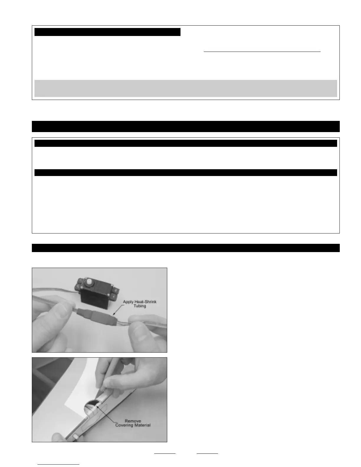
❑ To prevent the plugs from pulling apart during assembly, or worse,
during flight, secure the plugs together, using a short piece of 3/8"
diameter heat-shrink tubing. Use a heat gun to shrink the tubing tight.
❑ Using a modeling knife, cut away and remove the covering material
from over the aileron servo lead exit hole in the top of the wing panel.
The hole is located on the edge of the root rib, 4-3/4" in front of the
trailing edge.