20
❑ Remove the nylon mounting straps and drill four 1/16" diameter pilot
holes into the fuselage at the marks you drew.
❑ Install the two nylon mounting straps, using four M2 x 10mm wood
screws, to secure the tail skid into place.
❑ Pacer Z-42 Blue Threadlocker
❑ # 2 Phillips Head Screwdriver
❑ Adjustable Wrench (2)
❑ Excel Modeling Knife
❑ Electric Drill
❑ 5/32" Drill Bit
❑ Ernst Airplane Stand
❑ Ruler
❑ Pencil
❑ 220 Grit Sandpaper w/Sanding Block
YOU'LL NEED THE FOLLOWING PARTS FROM THE KIT:
YOU'LL NEED THE FOLLOWING TOOLS AND SUPPLIES:
SECTION 11: LANDING GEAR INSTALLATION
❑ (1) Aluminum Landing Gear Bracket
❑ (2) Molded Wheel Pants
❑ (2) Main Gear Wheels
❑ (2) M4 x 35mm Threaded Axles
❑ (3) M4 x 16mm Machine Screws
❑ (4) M4 Lock Nuts
❑ (2) Nylon Spacers
❑ (2) M2 x 10mm Flange-Head Wood Screws
❑ (13) M4 Flat Washers
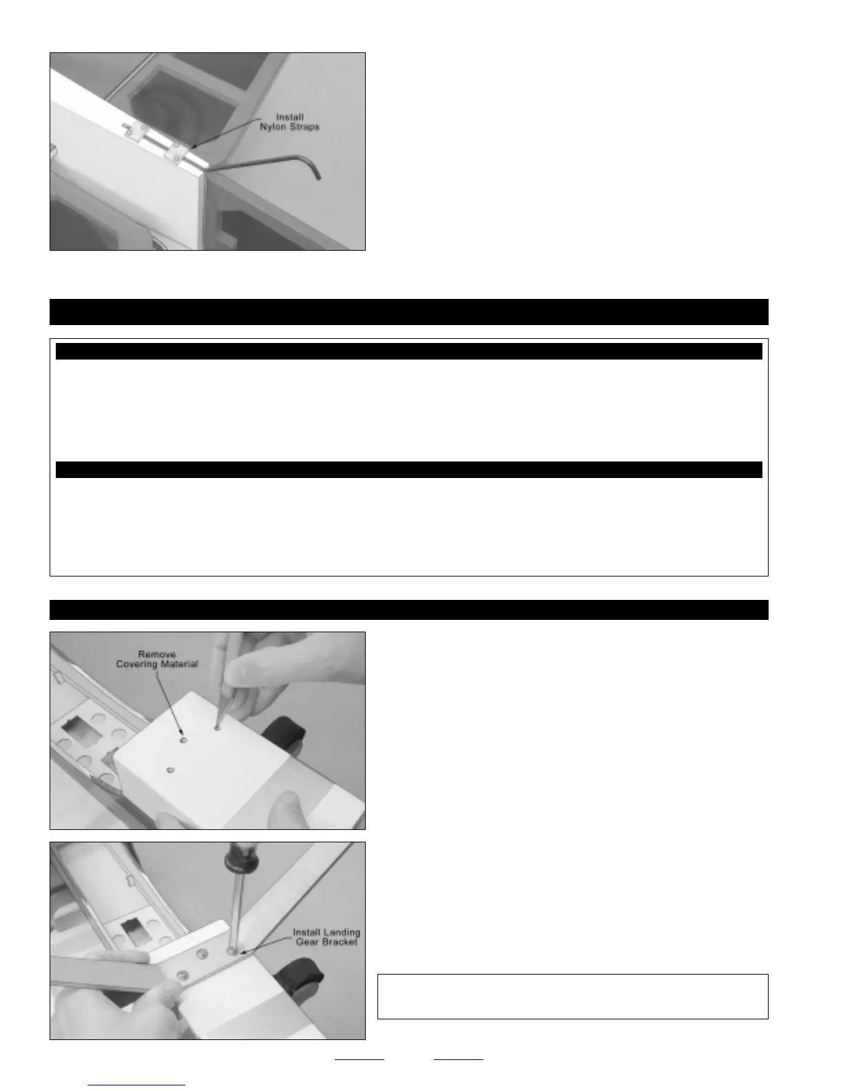
STEP 1: INSTALLING THE LANDING GEAR BRACKET
❑ Using a modeling knife, cut away and remove the covering material
from over the three predrilled landing gear mounting holes in the bottom
of the fuselage. The location of the holes should be visible underneath
the covering material.
❑ Install the aluminum landing gear bracket to the bottom of the
fuselage, using three M4 x 16mm machine screws and three M4 flat
washers.
☞
Blind nuts have been preinstalled into the landing gear mounting
block to thread the screws into.
✦✦
✦✦
✦IMPORTANT
✦✦
✦✦
✦ We suggest applying Blue Threadlocker to the
machine screws so that they don't come loose during flight.
Continued On Next Page
☛☛
☛☛
☛