39
☞
Before gluing the canopy into place, clean the inside of it to remove any fingerprints, dust and small debris.
❑ When satisfied with the alignment, carefully glue the canopy into place, using a thin layer of Pacer Formula 560 Canopy Glue.
Remove any excess glue before it dries, using a paper towel and water, and use pieces of masking tape to hold the canopy in
place until the glue fully cures.
SECTION 20: FINAL ASSEMBLY
❑ # 1 Phillips Head Screwdriver
❑ Excel Modeling Knife
❑ Scissors
❑ Electric Drill
❑ 5/64" Drill Bit
❑ Masking Tape
YOU'LL NEED THE FOLLOWING PARTS FROM THE KIT:
YOU'LL NEED THE FOLLOWING TOOLS AND SUPPLIES:
❑ (1) Decal Set
STEP 1: INSTALLING THE RECEIVER, BATTERY PACK AND SWITCH
✦✦
✦✦
✦IMPORTANT
✦✦
✦✦
✦ We don't suggest permanently installing the receiver and battery pack until you have balanced the airplane.
How the airplane initially balances will determine where you need to mount the receiver and battery pack.
❑ Wrap the receiver and battery pack in foam rubber to protect them from vibration. Use masking tape or rubber bands to hold the
foam in place. Do not wrap the foam rubber too tightly or the vibration dampening quality will be reduced.
❑ After you've found the final location of the receiver and battery pack, mount them into the fuselage using your favorite method.
Strips of Velcro
®
work well or sandwich them in place using a couple of scraps of balsa wood glued between the fuselage sides. A
flat battery pack can be mounted in the fuel tank compartment, if necessary.
✦✦
✦✦
✦IMPORTANT
✦✦
✦✦
✦ If you're using a lightweight two-stroke engine, it may be necessary to mount the battery pack in the fuel tank
compartment to balance the airplane.
❑ After installing the receiver, drill a 5/64" diameter hole through the fuselage floor (behind the wing saddle) for the antenna to exit.
Unwrap the receiver antenna and feed it out through the hole.
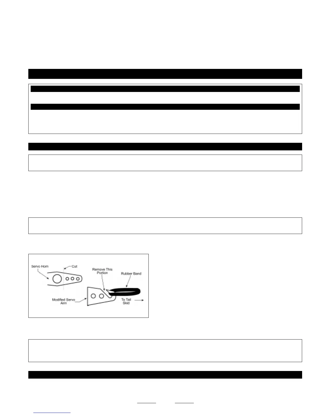
❑ Using a modeling knife, carefully make an antenna mount out of an
extra servo horn. Remove one of the arms and cut it into the shape shown.
❑ Use the modified servo arm and a rubber band to secure the end of
the antenna to the tail skid.
❑ Mount the switch to the fuselage side (opposite the muffler) and connect the battery lead to the switch, and the switch and servo
leads to the receiver.
✦✦
✦✦
✦IMPORTANT
✦✦
✦✦
✦ Make sure that the servo leads (including the aileron servo leads when the wing is installed) cannot interfere or
otherwise get caught in the rudder pushrods. You should take measures to secure the servo leads, so they can't get tangled in the
rudder pushrods during flight.
STEP 2: APPLYING THE DECALS
❑ Using a clean cloth, wipe the airframe down completely to remove any dust, oil and fingerprints, then cut out each of the decals
and apply them to the airframe, using the box cover photos for reference.