4
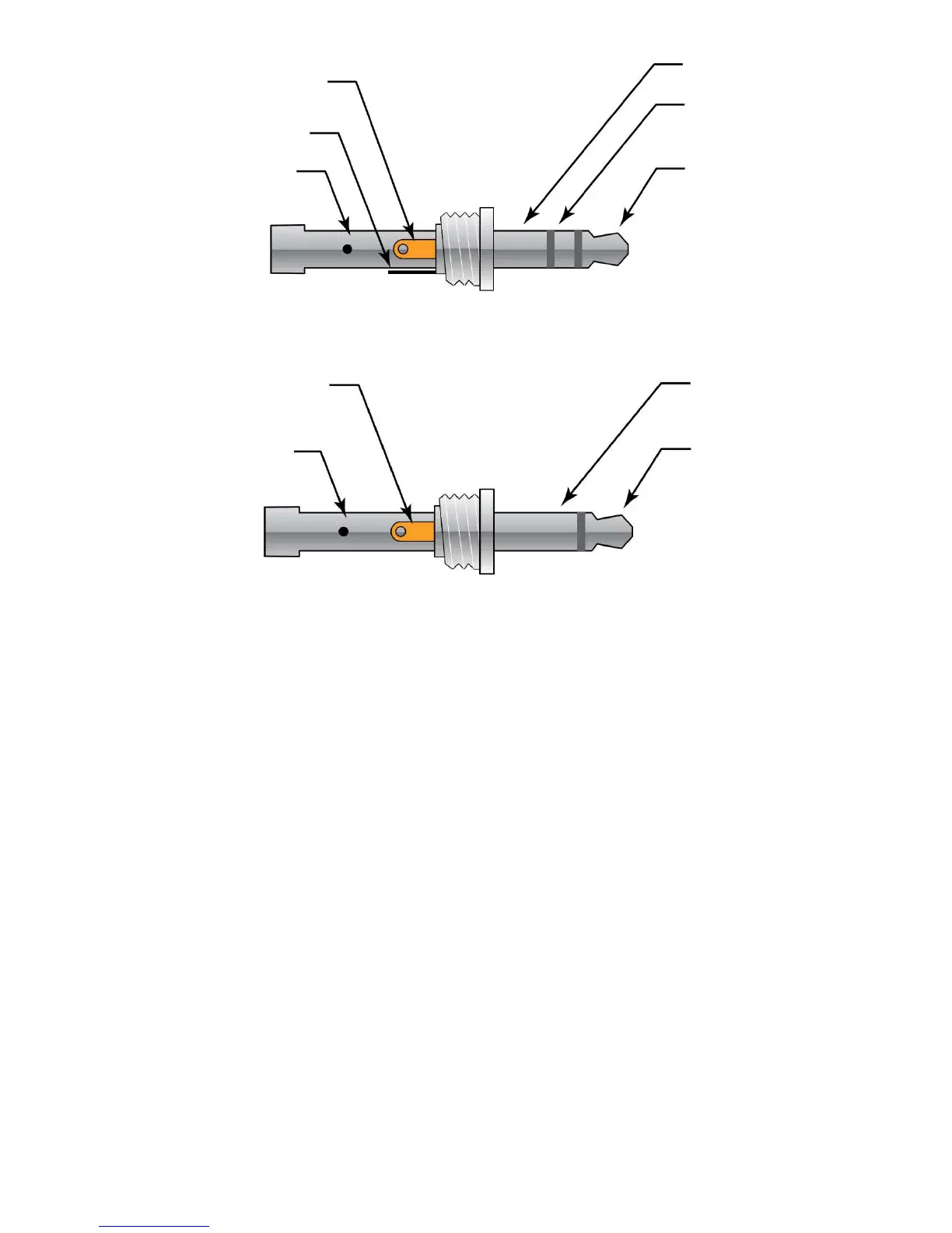
Figure 3 Input Connector Detail (Stereo plug)
Figure 4 Output Connector Detail (Mono plug)
With no external input, the output jack provides a TTL compatible pulse
from the strobe’s internal oscillator. If an external input is applied, the
output pulse is in sync with the input pulse. This output pulse may be
used to trigger a second stroboscope synchronously to illuminate larger
areas. Many strobes can be “daisy chained”. The output jack of one
strobe is connected to the input jack of the next strobe causing all the
strobes to fl ash together and be controlled by the fi rst strobe in the chain.
Note: Cables should not exceed 8 feet or 2.5 meters in length in
order to comply with the CE rating of this product.
4.0 MODES OF OPERATION
The stroboscope has two basic modes of operation – INTERNAL and
EXTERNAL. The unit does not operate when in the Charging Mode.
Signal Output
Common (GND) Signal Output
Common (GND)
Signal Input
+3.2V Out to
Sensor
Common (GND)
Signal Input
+3.2V Out to
Sensor
Common (GND)