SCH2 Technical Manual TSP016.doc Issue 3.0 – January 2005
Money Controls 2005. All rights reserved.
Page 15 of 61
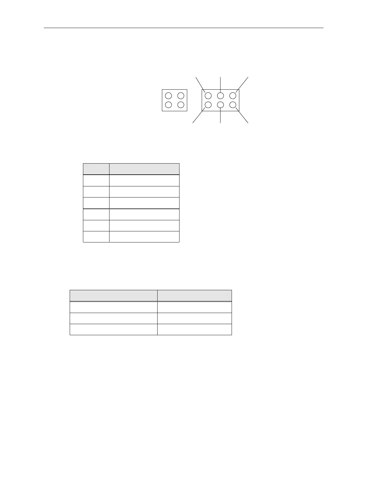
10.2 Auxiliary Connector Type
Figure 3: SCH2 Auxiliary Connector
PCB Connector
2.54mm ( 0.1inch ) pitch
Part No. : TBD
Keying Information
10.21 AUXILIARY CONNECTOR PINOUT
Pin Function
1 High Level Plate
3 Low Level Plate
5 Plate Common
2 High Level Link
4 Low Level Link
6Link Common
10.3 Operation
To notify the hopper software that level plate sensors are fitted, the link pins should be
connected as follows…
Mode Connections
High level plates only pin 2 to pin 4
Low level plates only pin 4 to pin 6
High & low level plates pin 2 to pin 4 to pin 6
Otherwise, no connections should be made.
The level plates themselves should be connected through the corresponding plate pin ( pin 1
for high level, pin 3 for low level ) and the plate common ( pin 5 ).
1 3 5
2 4 6