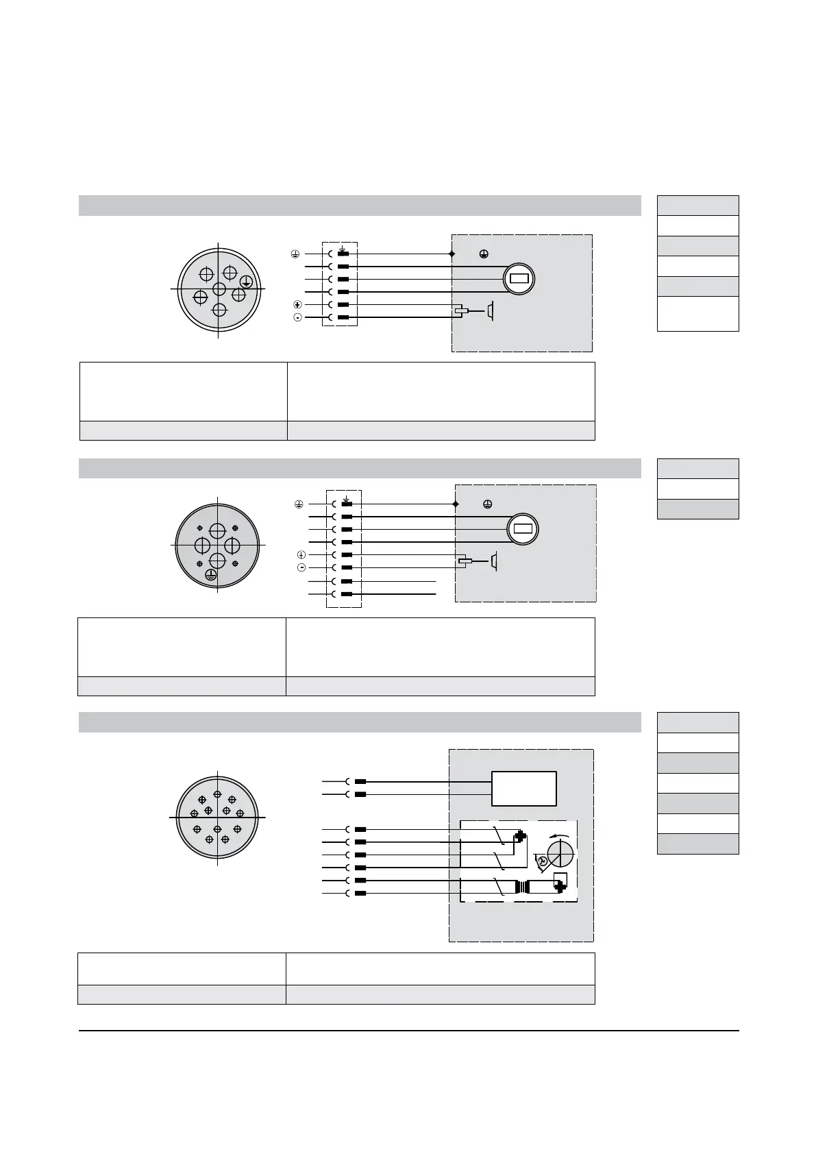
Wiring schematics: Power and Resolver Signal Connections
Verdrahtungsdiagramme: Anschlussbelegung Leistungsversorgung und Resolver
Schemi di collegamento: Connessione di segnale resover e di potenza
Schémas de câblage
Diagramas esquemáticos del cableado
Moog | Installation instructions G400 series
09/2008
ONLY VERSION WITH BRAKE
PROTECTIVE EARTH
6
-
W
+
V
U
5
1
2
4
MOTOR
5
4
1
6
2
Protective earth
U phase
V phase
W phase
Brake supply (+)
Brake supply (-)
N/S
Power connector Size 1
-
+
U
V
W
W
1
2
-
V
U
+
1
2
ONLY VERSION WITH BRAKE
PROTECTIVE EARTH
-
W
+
V
U
MOTOR
Protective earth
U phase
V phase
W phase
Brake supply (+)
Brake supply (-)
Vacant
Vacant
N/S
1
R2
8
S2
S4
R1
S1
S3
7
4
3
2
6
5
RESOLVER
11
4
3
5
6
12
9
10
2
1
7
8
Sin (+)
Sin (-)
Cos (+)
Cos (-)
TEMPERATURE
SENSOR
MOTOR
Vref (+)
Vref (-)
sensor
Temperature
TYPE
G-1
G-2
G-3
G-4
G-5 up to
G-5-x8
Power connector Size 1.5
TYPE
G-5-x9
G-6
Signal resolver connector
1)
TYPE
G-1
G-2
G-3
G-4
G-5
G-6
ONLY VERSION WITH BRAKE
PROTECTIVE EARTH
6
-
W
+
V
U
5
1
2
4
MOTOR
5
4
1
6
2
Protective earth
U phase
V phase
W phase
Brake supply (+)
Brake supply (-)
N/S
-
+
U
V
W
W
1
2
-
V
U
+
1
2
ONLY VERSION WITH BRAKE
PROTECTIVE EARTH
-
W
+
V
U
MOTOR
Protective earth
U phase
V phase
W phase
Brake supply (+)
Brake supply (-)
Vacant
Vacant
N/S
1)
See order information; Feedback option: 01
Cable scheme 4x1.5mm
2
power (G-1 to G-4)
4x2.5mm
2
power (G-5 upto G-5-x8)
2x1,0 mm
2
brake
outer shield
Mating connector loose Model number: C08365-001
Cable scheme 4x6.0mm
2
power (565V
DC
motors)
4x10mm
2
power (325V
DC
motors)
2x1,0 mm
2
brake
outer shield
Mating connector loose Model number: B47711-001
Cable scheme 4x2x0,25mm
2
, stranded wires,
twisted paired, outer shield
Mating connector loose Model number: C08485-001
13

 Loading...


