28
Rev. 1.0
2016/7/30
SS03/05/10-EC Hardware Manual
+86-400-820-9661
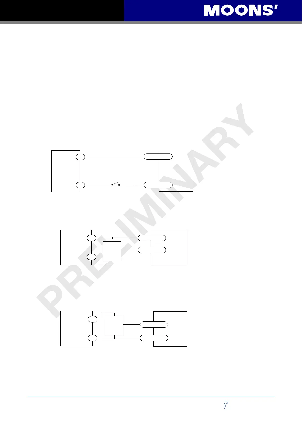
3.1 Digital Inputs
3.1.1 X1, X2, X3 and X4 Digital Inputs
X1, X2, X3 and X4: optically isolated, dierential, 5-24VDC, minimum pulse width 250ns, maximum
pulse frequency 2MHz
• X1 can be used as general purpose input.
• X2 can be used as general purpose input.
• X3 can be used as CW limit input or general purpose input.
• X4 can be used as CCW limit input or general purpose input.
Use Step-ServoQuickTuner software for X1, X2, X3 and X4 function conguration.
The following graphs show some common connection methods for the inputs:
SS-EC
Drive
Switch or Relay
(closed = logic Low)
X1/2/3/4-
X1/2/3/4+
-
+
5-24
VDC
Power
Supply
SS-EC
Drive
NPN
Output
X1/2/3/4-
X1/2/3/4+
output
+
–
5-24
VDC
Power
Supply
-
+
SS-EC
Drive
PNP
Output
X1/2/3/4+
output
+
–
X1/2/3/4-
5-24
VDC
Power
Supply
-
+
Connecting the inputs to a switch or relay
Connecting the inputs to an NPN type output
Connecting the inputs to a PNP type output