-21-
Braking Systems - Electric
Magnet Amperes Chart
Brake
Size
Amps/
Magnet
Two
Brakes
Four
Brakes
Six
Brakes
Magnet
Ohms
7" x 1 1/4" 2.5 5.0 10.0 15.0 3.9
10" x 1 1/2" 3.0 6.0 12.0 18.0 3.2
10" x 2 1/4" 3.0 6.0 12.0 18.0 3.2
12" x 2" 3.0 6.0 12.0 18.0 3.2
12 1/4" x 2 1/2" 3.0 6.0 12.0 18.0 3.2
12 1/4" x 3 3/8" 3.0 6.0 12.0 18.0 3.2
If a resistor is used in the brake system, it must be set at zero or bypassed
completely to obtain the maximum amperage reading. Individual amperage
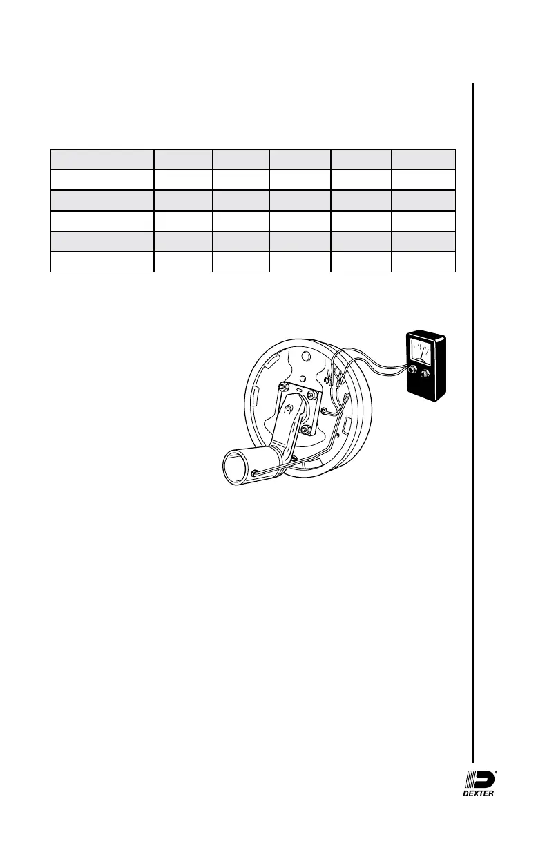
draw can be measured by
inserting the ammeter in the line
at the magnet you want to check.
Disconnect one of the magnet
lead wire connectors and attach
the ammeter between the two
wires. Make sure that the wires
are properly reconnected and
sealed after testing is completed.
The most common electrical
problem is low or no voltage and amperage at the brakes. Common causes of
this condition are:
1. Poor electrical connections
2. Open circuits
3. Insufcient wire size
4. Broken wires
5. Blown fuses (fusing of brakes is not recommended)
6. Improperly functioning controllers or resistors
Another common electrical problem is shorted or partially shorted circuits
(indicated by abnormally high system amperage). Possible causes are:
1. Shorted magnet coils
2. Defective controllers
3. Bare wires contacting a grounded object
AMMETER