21
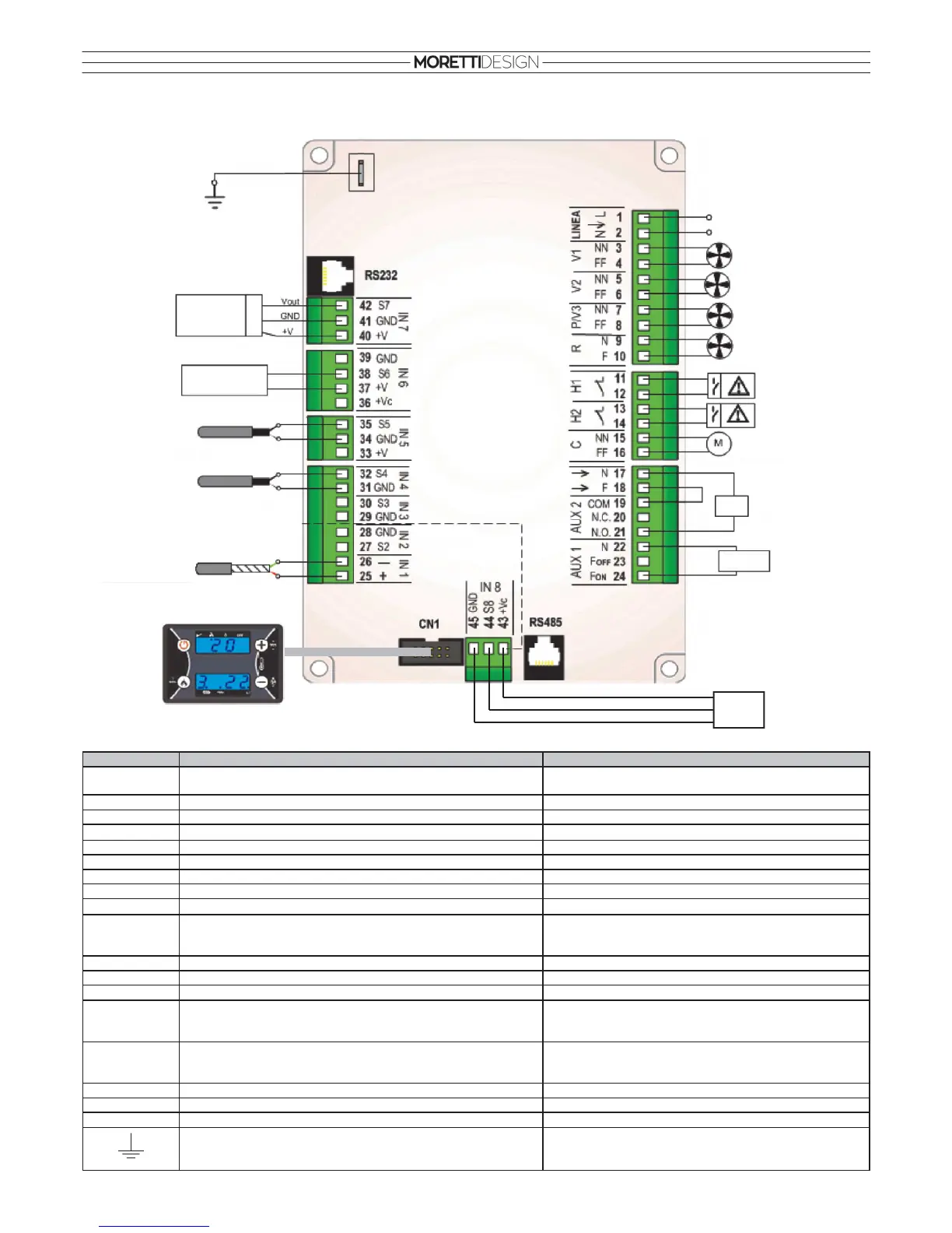
CONTROL UNIT - FOR C (DOUBLE HOT AIR DUCT) MODELS
Safety
Thermostat
Pressure Switch
Exhaust Fan
Heating Fan
Heating Fan 2
Heating Fan 3
Auger
Aux
Ignition
Resistance
LINE
(230V 50Hz)
Sonda Fumi
Encoder
Remote Room
Thermostat
Remote Room
Thermostat 2
Micro
Emergency Control Panel
Flowmeter (FCS)
Pin Function Technical Features
1-2
Main Power Supply
Version 230Vac ± 10% 50/60 Hz
Version 110Vac ± 10% 50/60 Hz
3-4
Exhaust Fan Triac, powered output (Max 0,8 A)
5-6
Heating Fan Triac, powered output (Max 0,8 A)
7-8
Heating Fan 2 Triac, powered output (Max 0,8 A)
9-10
Heating Fan 3 Triac, powered output (Max 0,8 A)
11-12
Safety Thermostat Contact On/Off Normally Closed
13-14
Pressure Switch Contact On/Off Normally Closed
15-16
Auger Triac, powered output (Max 0,8 A)
22-24
Ignition Resistance Relé 3A max
25-26
Exhaust Fume probe
Thermocouple K 500 °C Max
25: Red (+)
26: Green (-)
31-32
Remote Room Thermostat 2 NTC 10K @25°C 120°C Max
34-35
Remote Room Thermostat NTC 10K @25°C 120°C Max
37-38
Micro switch -
40-41-42
Encoder
40: +5V
41: GND
42: signal
CN1
Connector for the Emergency Control Panel Flat Cable
RS232
Serial connector Serial Port RS232
RS485
Serial connector Serial Port RS485
Connection to ground system
ALWAYS CONNECT
-
43-44-45
Flowmeter (FCS)
43: Red
44: Yellow
45: Black