Page43SYSTEM
Perforating
*Perforatorstripper177-05-01
Allofthebladesandanvilsaresuppliedwithfixings.
StandardPartNumber
*Itisrecommendedthatformultipleperforations,aseparateperforatorstripperisusedfor
everyperforatingbladesetfittedinthecreasingunit.
1.Turnthemainssupplytothemachine‘off’.
2.Opentheperforatorassemblytogetaccesstothedrivewheelsandhubs.
3.Locateandremovetheblades/anvilsfromthedespatchkitsuppliedwiththe
machine.
4.Usingthe2mmallenkey(supplied),loosenthedrivewheelthatistoaccommodate
theblades.
5.Slidethedrivewheelawayfromanyobstructingdrivewheelsorhubsinorderto
mounttheblades.
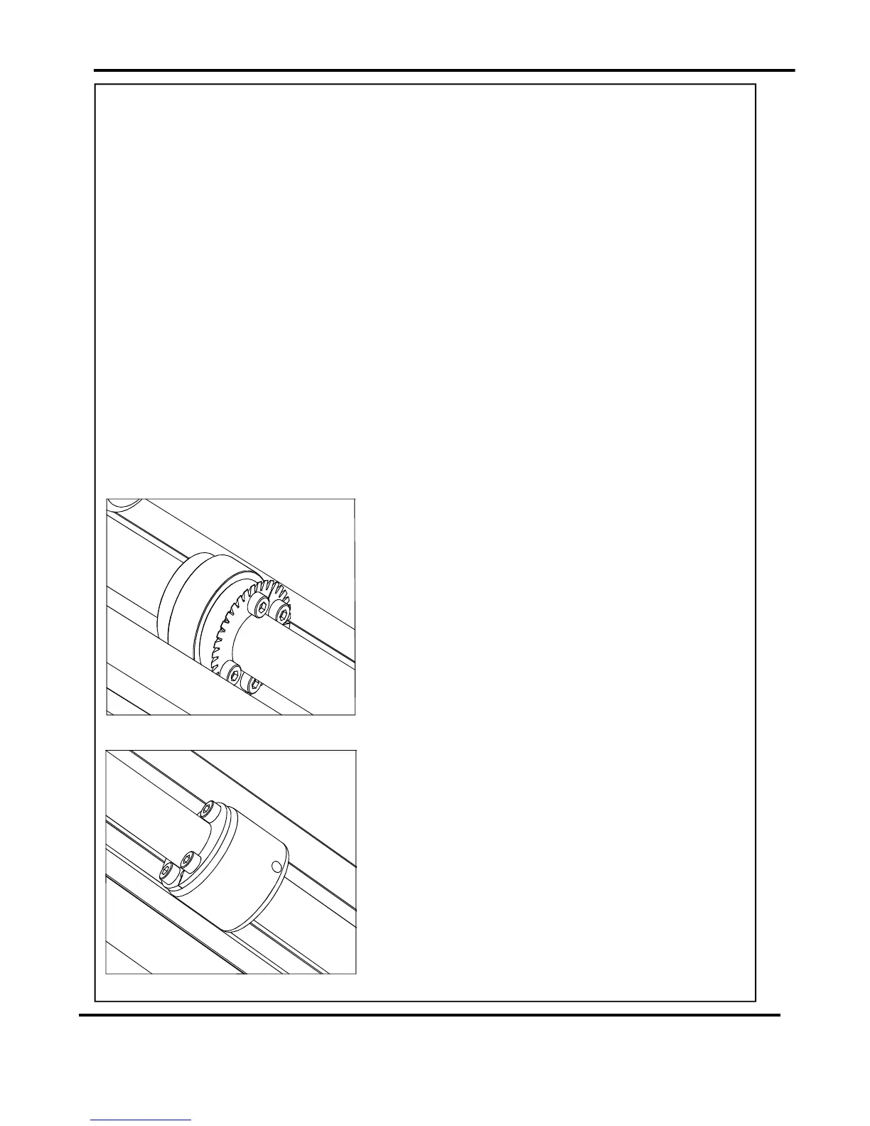
6.Usingthe2.5mmallenkey(supplied),takeone
halfofthematchingpairofbladesandmounton
tothedrivewheel.Donotsecuretheblade.
7.Mounttheotherhalfofthebladetothedrive
wheelasshown(FIG37.1).Securethebladesto
thewheelensuringnottoovertightengrubscrew.
8.Markonasinglesheetthedesiredperforating
position.Feedthesheetthroughthemachine
manuallyuntilthemarkcanbeseen.Usethis
marktoassistinfixingthepositionofthe
perforatingdrivewheeltotherollerdriveshaft.
9.Usingthe2mmallenkey,loosenthedrivehub
nearesttheperforatingdrive.Slidethedrivehub
awayfromanyobstructingdrivewheelsorhubs
inordertomounttheanvils.
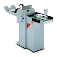
10.Usingthe2.5mmallenkey,takeonehalfofthe
matchingpairofanvilsandmounttothedrive
hub.Donotsecuretheanvil.
11.Mounttheotherhalfoftheanviltothedrivehub
asshown(FIG37.2).Securetheanvilstothedrive
hubensuringnottoovertightenthegrubscrews.
Settingthemachine
FIG37.1
FIG37.2
DigiFoldPro