6. Operation
32
6.4 Engine driven welder operation
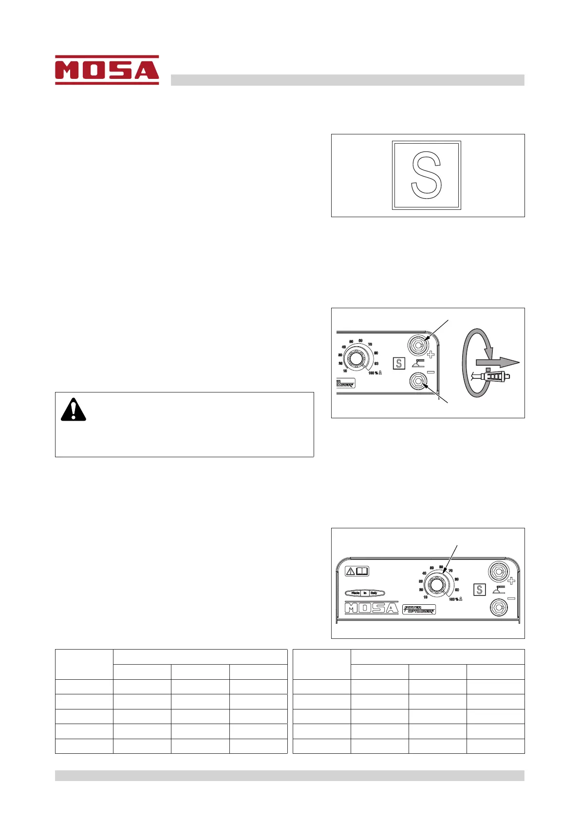
Thissymbol(standardEN60974-1–safetyrequirements
for arc welding equipment) indicates that the engine driv-
en welder is designed to be used in environments with an
increased risk of electric shock.
• To reduce the risk of electromagnetic interference, use
the minimum length of welding cables and keep them
closeandlow(e.g.ontheoor).
D5260960
• For welding cables up to 10 m long, a section of 35 mm
2
is recommended; if it is necessary to use longer
cables, increase the section proportionally.
• All electrodes on the market can be used.
6.4.1 Welding cables connection
Thecablesmustbeconnectedwiththeengineo.
1 - Insert the welding cable plugs in sockets (1) and turn
them clockwise to lock them.
2 - Make sure that the grounding clamp - whose cable must
be connected to the negative socket or to the positive
socket according to the type of electrode - makes a
correct contact and that it is as close as possible to the
welding position.
WARNING
• Make sure that the two polarities of the welding
circuit do not come into contact with each other.
3 - Carefully tighten the output cables to the welding sockets. If they are loose, they can cause overheating
issues and damage bushings, cables, etc.
1
1
D5261090
6.4.2 Adjusting the welding current
The welding current is continuously regulated by the knob
(2).
• If brought to a minimum (fully rotated counter-clockwise),
the output current is about 20A.
• If rotated to a maximum (fully rotated clockwise), the
current is adjusted to its maximum value.
1 - Place the knob (2) on the required current value accord-
ing to the electrode diameter and type.
2
D5261100
Knob
reference
Welding current range
Knob
reference
Welding current range
MW 200 MW 250 Accuracy MW 200 MW 250 Accuracy
10 % 20A 25A ± 10 % 60 % 120A 150A ± 10 %
20 % 40A 50A ± 10 % 70 % 140A 175A ± 10 %
30 % 60A 75A ± 10 % 80 % 160A 200A ± 10 %
40 % 80A 100A ± 10 % 90 % 180A 225A ± 10 %
50 % 100A 125A ± 10 % 100 % 200A 250A ± 10 %


 To Next Page