35
6. Operation
R76
R13
(2)
(1)
(3)
(2)
(1)
(3)
D5261160
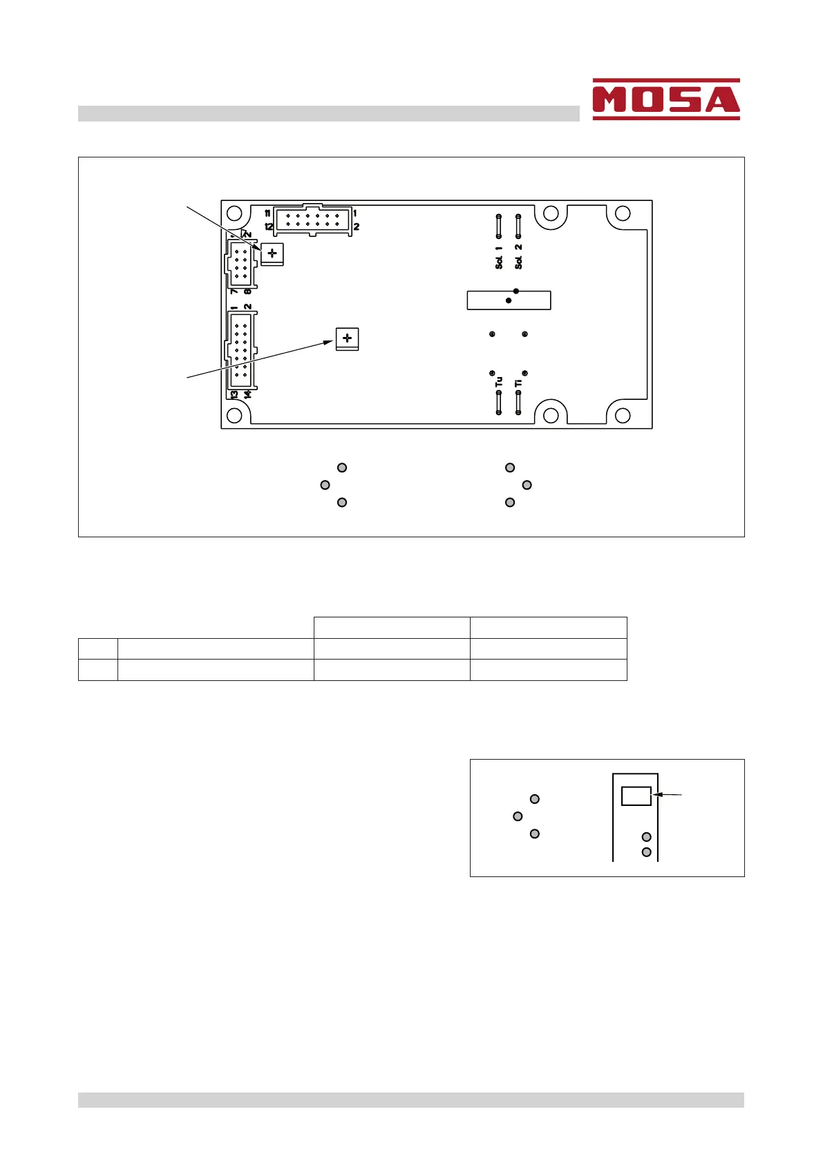
Each time the welding board is replaced, you should check the settings before installing it on the engine
driven welder.
Check the settings by measuring the ohmic resistance of the 2 trimmers R13 and R76, and checking that
they correspond to the values indicated in the following table.
Magic Weld 200 Magic Weld 250
R13 Max. welding current
5.5kΩ±5% 3.1kΩ±5%
R76 Power Optimizer 45-46kΩ 43-44kΩ
Resistance should be measured between terminals (1) and (3) of the two trimmers R13 and R76.
Terminal (2) should not be considered.
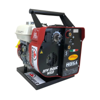
Example of R13 set-up for the Magic Weld 200 model
(2)
(1)(+)
(+)
5,5 kΩ
(–)
(–)
(3)