Radio Assembly — Detailed 2-11
7.5 Chassis and Front Cover Assembly
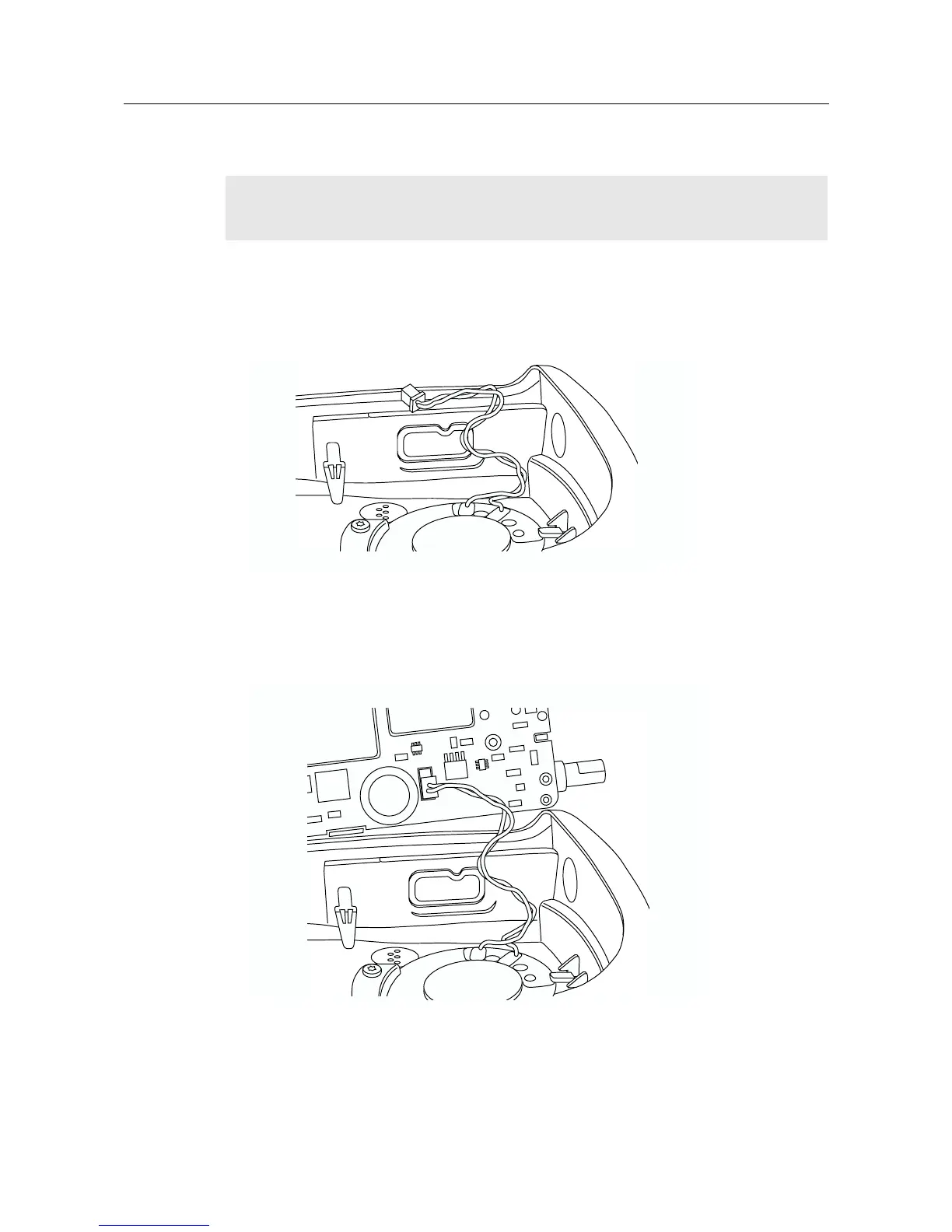
1. Dress and connect the speaker wires.
a. Form the wires into an “M” shape so it can collapse on itself like an accordion with all of
the wire up in the top corner of the radio away from the shields. Place three bends in the
wires spaced approximately 1cm apart to give the wire an “M” shape (Figure 2-11).
b. Bend the wires up from the speaker so the wires are positioned toward the top of the
radio (Figure 2-11).
c. Connect the speaker wire assembly into the 2-pin connector on the main board and
bend the wires at the board connector so the wires are positioned toward the top of the
radio (Figure 2-12).
2. Slide the volume potentiometer and frequency switch shafts into their respective holes in the front
cover. Look through the accessory connector opening to make certain that the wires are not pinched.
NOTE:
Care should be taken when dressing the speaker wires to avoid pinching them between the
speaker magnet and shield, under the microphone boot or between the accessory
connector and housing.
Figure 2-11 Bend the Wires into an “M” Shape
Figure 2-12 Connect Speaker Wire Assembly

 Loading...


