2-16 MAINTENANCE
10.0 Test Equipment
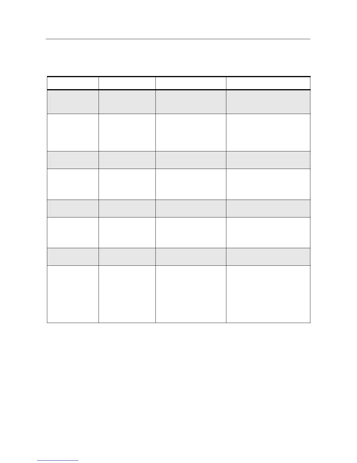
Table 2-2 lists test equipment required to service the CP040 Radio and other two-way radios.
Table 2-2 Recommended Test Equipment
Motorola Part No. Description Characteristics Application
R2600 series Comms System
analyzer (non MPT)
This item will substitute for
items with an asterisk (*)
Frequency/deviation meter and
signal generator for wide-range
troubleshooting and alignment
*R1074_ Fluke 87 digital multi-
meter
True RMS metering,
200 kHz frequency
counter, 32-segment
bargraph with backlit
display
Digital voltmeter is
recommended for AC/DC
voltage and current
measurements
*R1377_ AC voltmeter 1mV to 300mV, 10 mega-
ohm input impedance
Audio voltage measurements
R1611_ Dual channel
100 MHz
oscilloscope
(Agillent)
Two-channel, 100 MHz
bandwidth, 200M sample
rate/sec, 2MB memory/
channel
Waveform measurements
S1339_ RF millivolt meter 100µV to 3V RF, 10 kHz to
1 GHz frequency range
RF level measurements
*R1013_ or
*R1370_
SINAD meter or
SINAD meter with
RMS
Without RMS audio
voltmeter or
With RMS audio voltmeter
Receiver sensitivity
measurements
S1348D Programmable DC
power supply
0-20V DC, 0-5 amps,
current limited
Bench supply for 7.5 V DC
R1440A
0180305F14
0180305F30
0180305F39
RLN4610A
T1013
Wattmeter,
Plug-in Element
Plug-in Element
Plug-in Element
Carry case
RF Dummy Load
Thruline 50-Ohm, ±5%
accuracy
10W, 25 - 60 MHz
10W, 100 - 250 MHz
10W, 200 - 500 MHz
Wattmeter and
6 elements
Transmitter power output
measurements

 Loading...


