Chapter 3 Controller Theory of Operation
3.1 Controller
The controller provides the following functions:
• interface with controls and indicators
• serial bus control of major radio circuit blocks
• encoding and/or decoding of selective signaling formats such as PL, DPL, MDC-1200 and
QuikCall II
• interface to CPS programming via the microphone connector
• storage of customer-specific information such as channel frequencies, scan lists, and signaling
codes
• storage of factory tuning parameters such as transmitter power and deviation, receiver squelch
sensitivity, and audio level adjustments
• power-up, power-down and reset routines
Figure 6-3 (VHF) shows the interconnection between the controller and the various other radio
blocks. Figure 6-9 show the connections between the following circuit areas which comprise the
controller block:
• microprocessor circuitry
• audio circuitry
• DC regulation circuitry (refer to Chapter 2, DC Regulations and Distribution.)
• rotary and pushbutton controls and switches
• option board interface
The majority of the circuitry described below is contained in the (VHF) Microprocessor Circuitry
schematic diagrams (Figure 6-10). Portions are also found in the Audio and DC Regulation
schematics (Figures 6-11 and 6-12).
3.1.1 Microprocessor Circuitry
The microprocessor circuitry includes microprocessor (U401) and associated EEPROM, S-RAM (not
used in EP450 models), and Flash ROM memories. The following memory IC's are used:
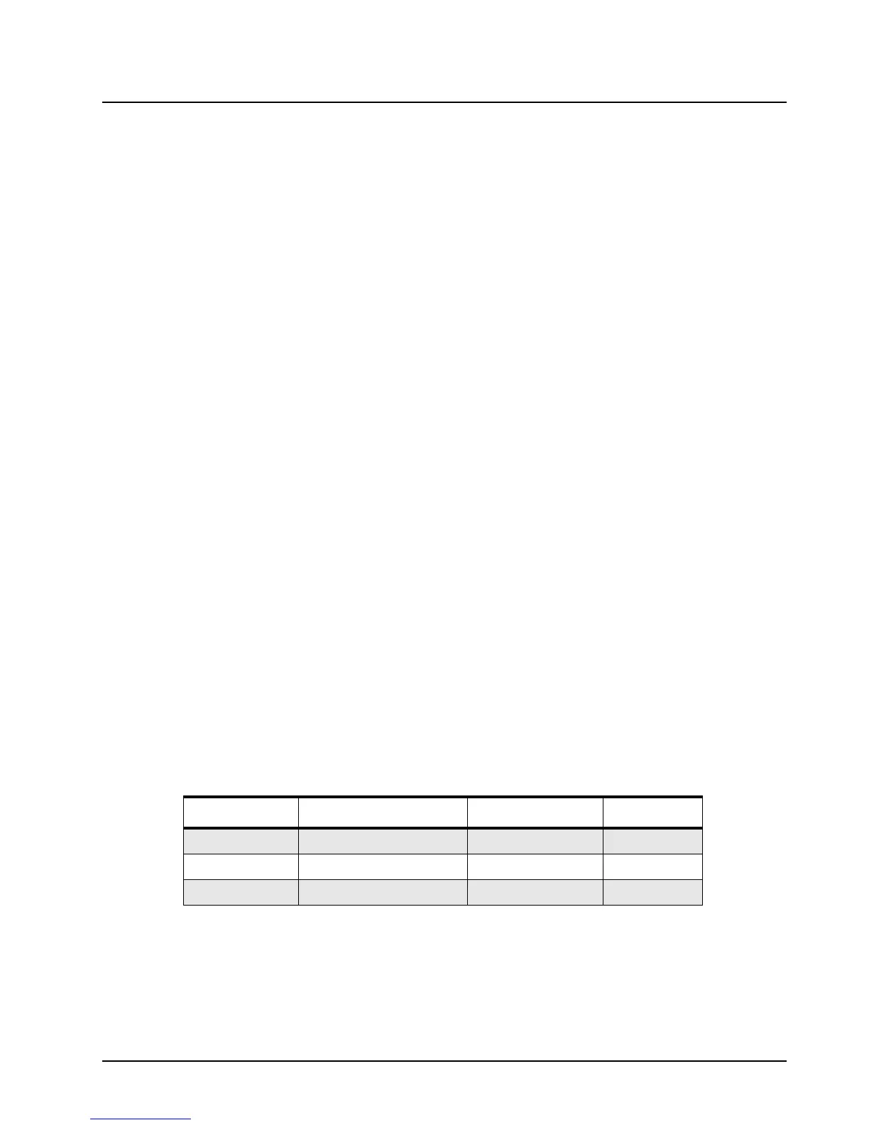
Table 3-1. Radio Memory Requirements
Reference No. Description Type Size
U402 Serial EEPROM AT25128 16K x 8
U403 Static RAM (not used)
U404 Flash ROM AT49LV001N_70 V 128K x 8

 Loading...


