November 24, 2003 HKLN4216A
4-2 VHF Theory Of Operation: VHF Receiver
constant at 6.2 mA regardless of device and temperature variations, for optimum dynamic range and
noise figure.
The output of the RF amplifier is applied to the interstage filter, a fixed-tuned 3-pole series-coupled
resonator design having a 3 dB bandwidth of 58 MHz and insertion loss of 1.8 dB. This filter has an
image rejection of 42 dB at 235 MHz, with increasing attenuation at higher frequencies.
The output of the interstage filter is connected to the passive double-balanced mixer consisting of
components T41, T42, and CR41. This mixer has a conversion loss of 7 dB. High-side injection from
the frequency synthesizer is filtered by L40-L41 and C40-C44 to remove second harmonic energy
that may degrade half-IF spurious rejection performance. The injection filter has a 3 dB bandwidth of
52 MHz and an insertion loss of 1.5 dB. The filtered injection signal is applied to T42 at a level of +6
dBm.
The mixer output is applied to a diplexer network (L51-L52, C51, R51) which matches the 44.85 MHz
IF signal to crystal filter FL51, and terminates the mixer into 50Ω at all other frequencies
4.2.2 Receiver Back-End
The receiver back end is a dual conversion design. High IF selectivity is provided by FL51, a 4-pole
fundamental mode 44.85 MHz crystal filter with a minimum 3 dB bandwidth of + 6.7 kHz, a maximum
20 dB bandwidth of ±12.5 kHz, and a maximum insertion loss of 3.5 dB. The output is matched to IF
amplifier stage Q51 by L53 and C93. Q51 provides 16 dB of gain and a noise figure of 1.8 dB. The dc
operating current is 1 mA. The output of Q51 is applied to the input of the receiver IFIC U51. Diode
CR51 limits the maximum RF level applied to the IFIC.
The IFIC is a low-voltage monolithic FM IF system incorporating a mixer/oscillator, two limiting IF
amplifiers, quadrature detector, logarithmic received signal strength indicator (RSSI), voltage
regulator and audio and RSSI op amps. The second LO frequency, 44.395 MHz, is determined by
Y51. The second mixer converts the 44.85 MHz high IF frequency to 455 kHz.
Additional IF selectivity is provided by two ceramic filters, FL52 (between the second mixer and IF
amp) and FL53 or FL54 (between the IF amp and the limiter input). The wider filter FL53 is used for
20/25 kHz channel spacing, and the narrower filter FL54 is used for 12.5 kHz channels. When the
BW_SEL line is high, the two upper diodes in packages D51 and D52 are forward biased, selecting
FL53 for 20/25 kHz channels. When the BW_SEL line is low, the two lower diodes in packages D51
and D52 are forward biased, selecting FL54 for 12.5 kHz channels.
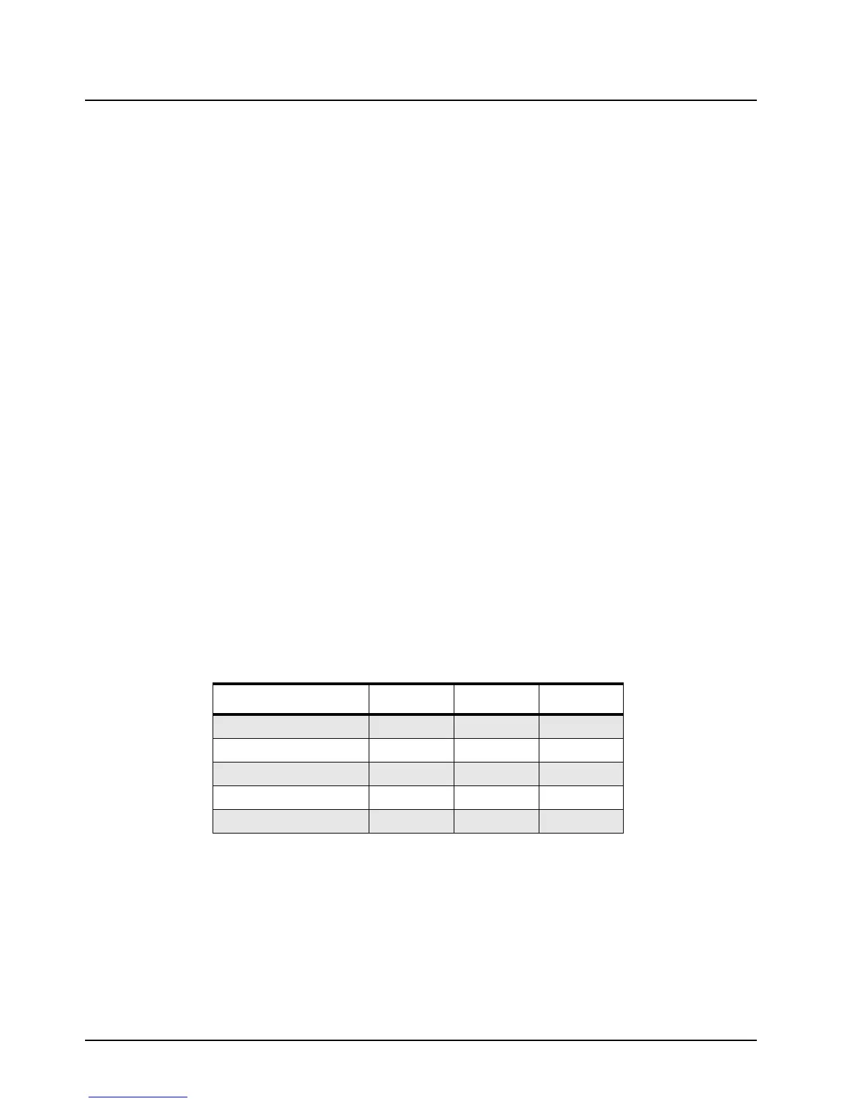
FL52 FL53 FL54
Number of Elements: 4 6 6
Insertion Loss: 4 dB 4 dB 4 dB
6 dB Bandwidth: 15 kHz 15 kHz 9 kHz
50 dB Bandwidth: 30 kHz 30 kHz 22 kHz
Stopband Rejection: 27 dB 47 dB 47 dB

 Loading...


