November 24, 2003 HKLN4216A
9-6 465-495 MHz UHF Theory Of Operation: UHF Frequency Generation Circuitry
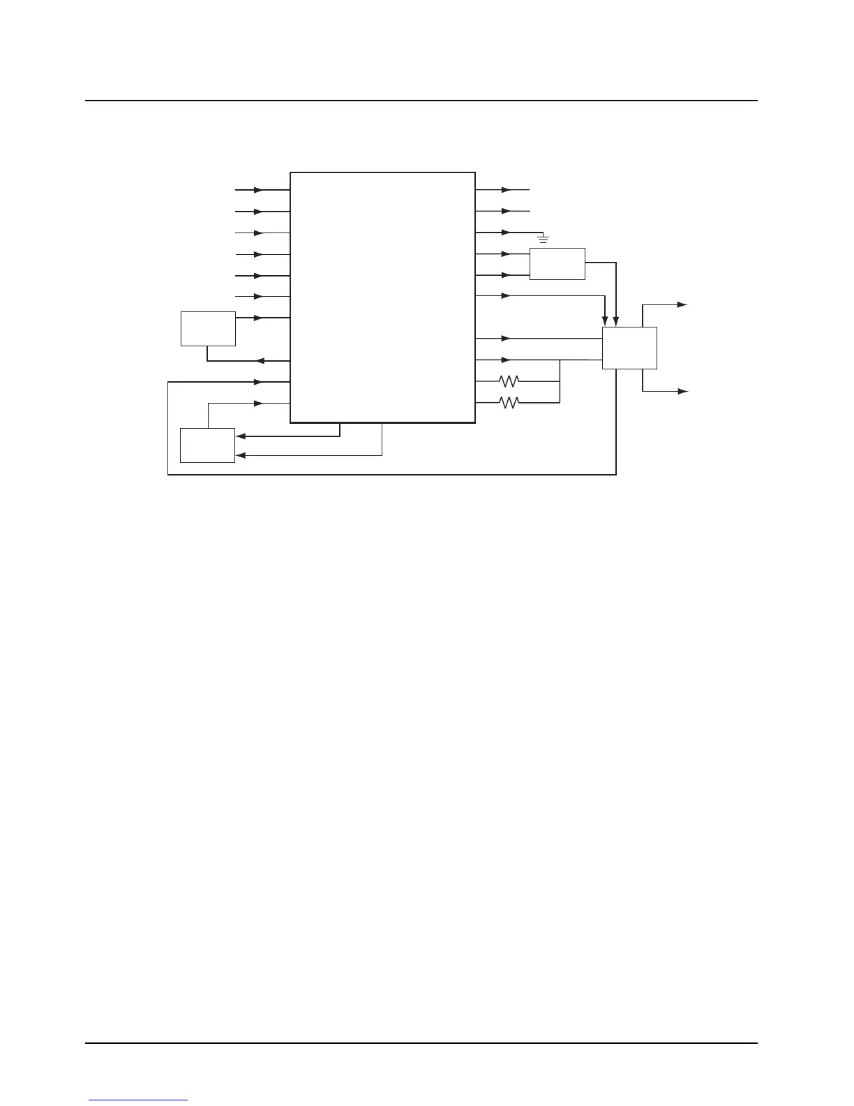
One of the auxiliary outputs of the synthesizer IC (AUX3, U201 pin 2) provides the TRB signal which
determines the operating mode of the VCO, either receive or transmit.
Figure 9-4. UHF Synthesizer Block Diagram
9.4.2 Voltage Controlled Oscillator (VCO)
The VCOBIC (U251), shown in Figure 9-5, in conjunction with the Fractional-N synthesizer (U201)
generates RF in both the receive and the transmit modes of operation. The TRB line (U251 pin 19)
determines which oscillator and buffer are enabled. A sample of the RF signal from the enabled
oscillator is routed from U251 pin 12 through a low pass filter, to the prescaler input of the synthesizer
IC (U201 pin 32). After frequency comparison in the synthesizer, a resultant DC control voltage is
used to steer the VCO frequency. When the PLL is locked on frequency, this voltage can vary
between 3.5 V and 10 V. L251 and C252 further attenuate noise and spurs on the steering line
voltage.
In the receive mode, the TRB line (U251 pin 19) is low. This activates the receive VCO and the
receive buffer of U251, which operate within the range of 420.15 to 450.15 MHz. The VCO frequency
is determined by tank inductor L254, C253-C257, and varactor D251. The buffered RF signal at U251
pin 8 is further amplified by Q280 and applied as RX_INJ to the low-pass injection filter in the receiver
front end circuit.
In the transmit mode, U251-19 is driven high by U201 pin 2, enabling the transmit VCO and buffer.
The 438-470 MHz RF signal from U251 pin 10 is applied as TX_INJ to the input of the transmitter
circuit via matching network C290-C291 and L291. TX VCO frequency is determined by L264, C263-
DATA
CLK
CEX
MODIN
V
CC
, 5V
XTAL1
WARP
PREIN
VCP
Reference
Oscillator
Voltage
Multiplier
Voltage
Controlled
Oscillator
2-Pole
Loop Filter
DATA (U401 Pin 100)
CLOCK (U401 Pin 1)
SYNTH_CS (U401 Pin 47)
MOD IN (U451 Pin 40)
+5V (U310 Pin 5)
7
8
9
10
13,30
23
25
32
47
VMULT2
VMULT1
BIAS1
SFOUT
AUX3
IADAPT
IOUT
GND
FREFOUT
LOCK
4
19
6,22,23,24
43
45
2
28
14
15
40
Filtered 5V
Steering
Line
LOCK (U401 Pin 56)
Prescaler In
LO RF
Injection
TX RF
Injection
(First Stage of PA)
FREF (U451 Pin 34)
39
BIAS2
41
+3V (U330 Pin 5)
V
DD
, 3V
MODOUT
U201
Low Voltage
Fractional-N
Synthesizer
5,20,34,36
TRB
VCO
Mod

 Loading...


