HKLN4216A November 24, 2003
UHF Troubleshooting Tables: Troubleshooting Table for Synthesizer 10-3
10.2 Troubleshooting Table for Synthesizer
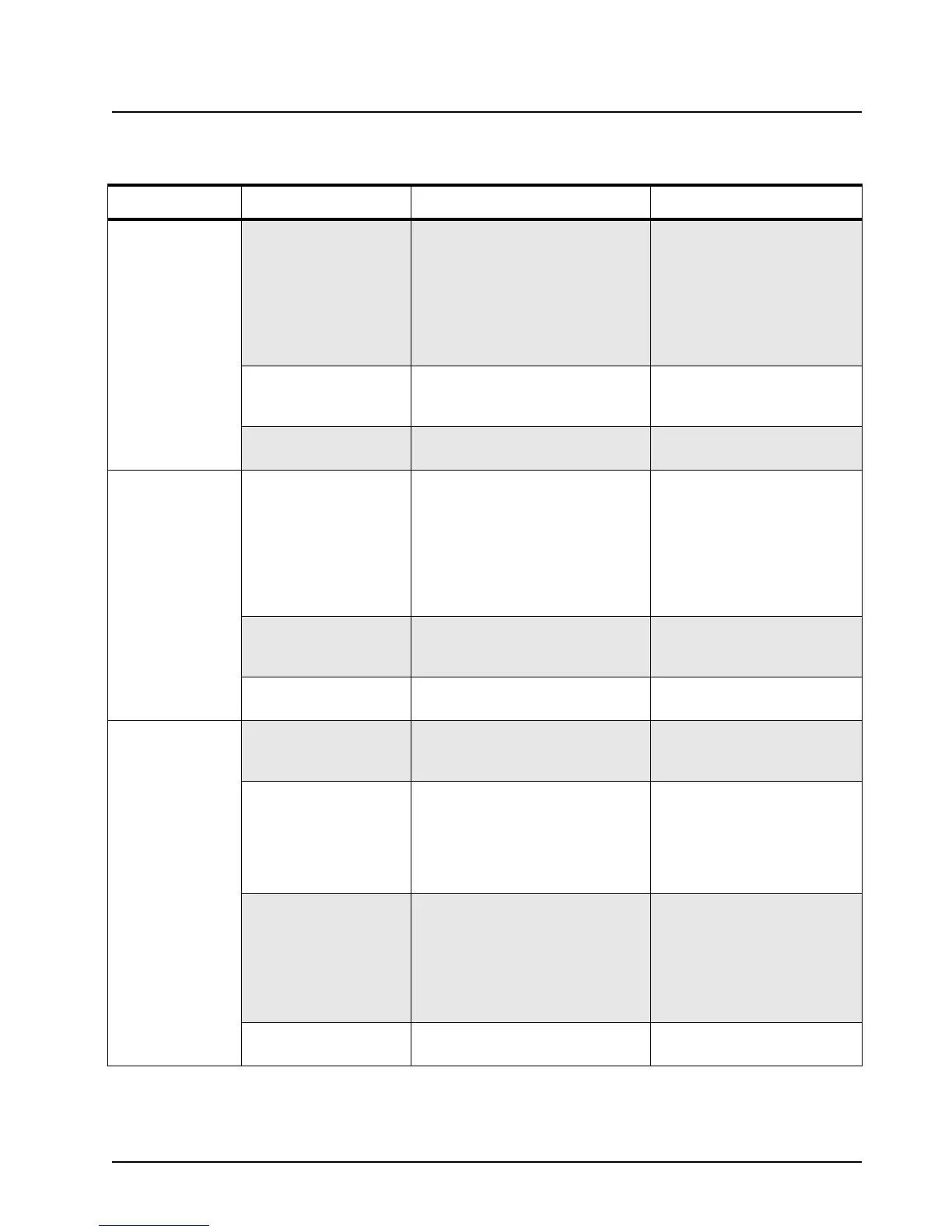
Table 10-2. Troubleshooting Table for Synthesizer
Symptom Possible Causes Procedure Corrective Action
Synthesizer Out of
Lock (RX mode
only)
1. VCO fault Verify oscillator is working, check RF
level at U251-10 per schematic.
Check dc voltages at U251 pin 2
through 6 and 10 per
Table 10-4.
Verify steering line voltage is
between ~3V and 10V.
Check VCO tank components
connected to U251-5 and 6.
Check for shorts/opens, replace
U251.
Check D251 and associated
components.
2. Synthesizer fault Verify TRB line (from U201-2 to
U251-19) is low in RX mode
Check for shorts, check U201
voltages per
Table 10-4,
replace U201 if incorrect.
3. Programming fault Verify RX channel programming is
correct.
Re-program if necessary.
Synthesizer Out of
Lock (TX mode
only)
1. VCO fault Verify oscillator is working, check RF
level at U251-10 per schematic.
Check dc voltages at U251 pins
1,3,4,10,15,16 per Table 10-4.
Verify steering line voltage is
between ~3V and 10V.
Check VCO tank components
connected to U251-15 and 16.
Check for shorts/opens, replace
U251.
Check D261 and associated
components.
2. Synthesizer fault Verify TRB line (U201-2 to U251-19)
is high (3V) in TX mode
Check for shorts, check U201
voltages per
Table 10-4,
replace U201 if incorrect.
3. Programming fault Verify TX channel programming is
correct.
Re-program if necessary.
Synthesizer Out of
Lock (RX and TX
modes)
1. VCO fault Check that RF level at U251-12 is at
least 150 mV (VHF) or -12 to -20
dBm (UHF)
If low/missing, check L276,
C276-7, R276.
2. Synthesizer fault Check that RF level at U201-32 is at
least 150 mV (VHF) or -12 to -20
dBm (UHF).
Verify steering line voltage is
between ~3V and 10V.
If correct, check/replace U201.
If incorrect, check R248 and
C241.
Check loop filter components
R243-5 and C243-5.
3. DC voltage fault Verify 4.5V dc at U201-28.
Verify 12.1V dc at U201-47
Check C231-233, etc., for
shorts. If OK check/replace
U201.
Check for 3V 1.05 MHz sq
waves at U201-14 and 15.
Check C218-228, D220-221.
4. Programming fault Verify channel programming is cor-
rect.
Re-program if necessary.

 Loading...


