EX500 Radio Disassembly — Detailed 3-7
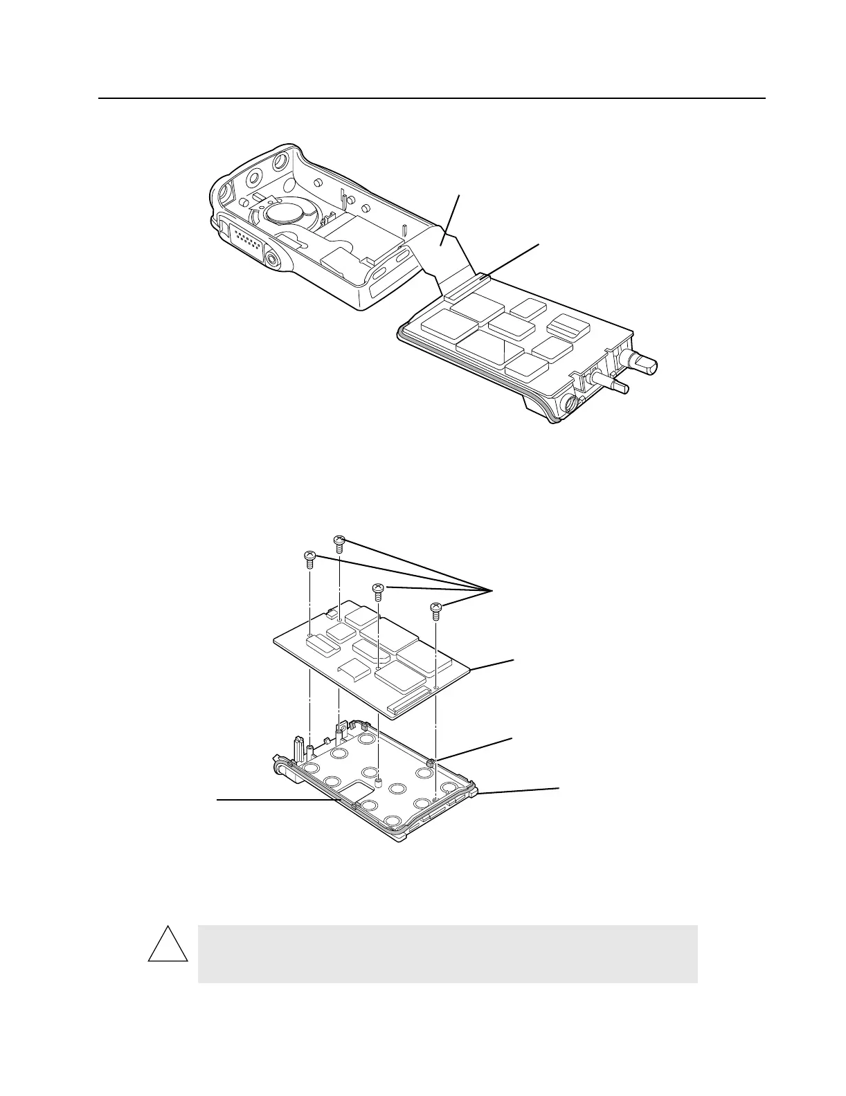
7. Lift the latches on the main circuit board to release the flexes from their connectors.
Figure 3-4 Unlatch Flex Connectors
3.6.2 Chassis Assembly Disassembly
Use a Philips head screwdriver to remove the four screws holding the main board to the chassis.
Figure 3-5 Remove Main Board from Chassis
1. Lift the main board from the chassis. (See Figure 3-5.)
2. Remove the four small O-ring retainers from their slots in the chassis. Note the alignment of the
retainers for reassembly.
CAUTION: Before removing the board, refer to the CMOS CAUTION
paragraph on page 3-2. Be sure to use ESD protection when handling
circuit boards.
Flex Connector
Latch
M2x4 Philips screws
Main Board
O-ring Retainers on chassis
(4 position)
Chassis
O-ring
slots
 Loading...