3-8 EX500 Radio Disassembly — Detailed
3. Remove the O-ring.
4. Slide off the ground contact from the top corner boss of the radio chassis.
3.6.3 Speaker, Microphone, and Universal Connector Flex Disassembly
1. Turn the screw at the bottom of the dustcover counterclockwise with your fingers. Lift the
dustcover out of its pocket.
2. Insert a flat bladed screwdriver in between the speaker and housing. Then pull up the screwdriver
to remove the speaker from the housing.
3. Pull the rubber microphone boot from its seated position. Unless you are replacing the
microphone, leave it in the boot.
4. Peel off the universal connector flex circuit escutcheon (label).
5. Pry the flex circuit (adhesive held) backer board away from the front cover, and remove the
universal connector tail of the speaker-microphone assembly through its opening in the front
cover.
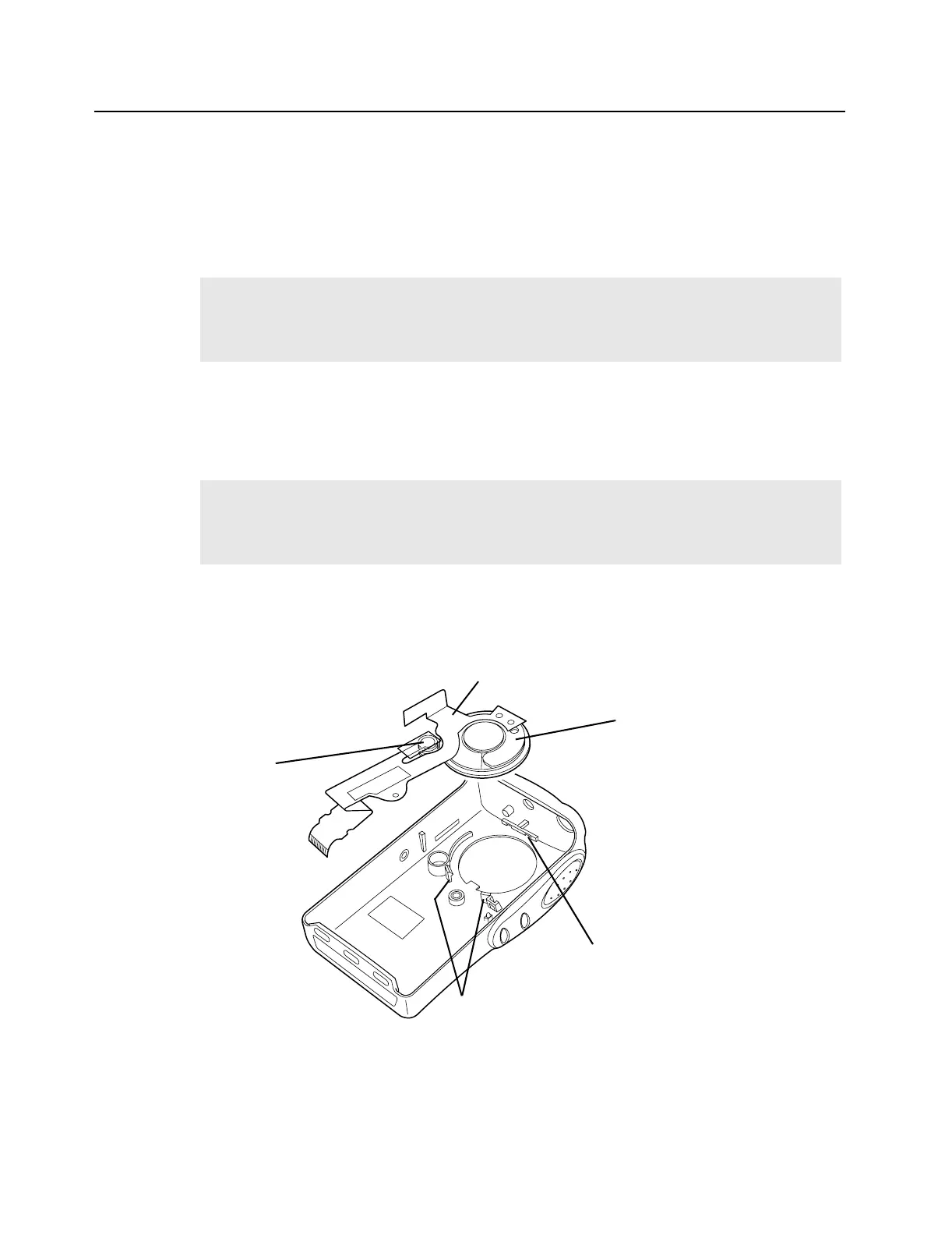
Figure 3-6 Removal of Speaker-Microphone Assembly
NOTE
The dustcover must be removed to remove the speaker-microphone assembly flex circuit.
The speaker is held in place with a two-legged retainer bracket. The bracket legs are
secured by the front cover slots. Be careful not to damage the speaker when removing the
retainer bracket.
NOTE
The speaker-microphone assembly flex circuit goes through the front cover wall to the
outside wall. To replace this assembly, you must peel off the universal connector escutcheon
label. (See item number 3 in the exploded view diagram on page 3-20.). The existing
escutcheon and speaker cannot be reassembled; a new part must be used.
Speaker
Flex Circuit
Microphone
Slot for Top Notch (speaker)
Speaker Catches
 Loading...