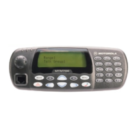
TROUBLESHOOTING MTM700 Portable Radio / Detailed Service Manual 9 - 1
CHAPTER 9
TROUBLESHOOTING
Section Introduction
This Chapter contains the following sections:
9.1 Troubleshooting for 380-430 MHz
9.2 Troubleshooting for 806-870 MHz
General
Troubleshooting faults in the radio require proper understanding of the different circuitry contained in
the radio. Since the radio contains a highly integrated system, the software and hardware functions
can not be separated easily. Thus, it is also necessary to understand the functioning of different ICs
and the role of the software in the operation of the radio. This service manual includes schematic
diagrams, circuit board layouts, block diagrams, and troubleshooting procedures, which help a tech-
nician to troubleshoot a malfunctioning circuit and detect a defective component.
NOTE: The CPS has no capability to tune the radio. Tuning the radio can only be performed at the
factory or at the appropriate Motorola Repair Centre.
Components replacement can affect the radio tuning and must only be performed by the
appropriate Motorola Repair Centre.
The radio is tuned and tested at the factory. The results of the tuning procedures are stored in a spe-
cial EEPROM. This information includes tuning and other system parameters. The area of the mem-
ory in the radio where the tuning information is stored is called the “codeplug”. A radio codeplug can
be read using the CPS programme.
Test Procedures
This section explains the procedures required to troubleshoot a MTM700 radio. Whenever possible
the radio should be tested and tuned using the automatic test system PATS before troubleshooting.
The PATS result file can provide useful hints to determine the failing circuitry section. Alternatively,
the Main Function Test Procedure can be performed to determine where to start troubleshooting.
After disassembling the board from the chassis you should check the board visually for bad solder-
ing or damaged components.
Troubleshooting Setup
Some of the troubleshooting procedures require an audio signal input or measurment of the audio at
the speaker output. The Test Set RLN4460 provides the correct microphone input and speaker out-
put circuitry. Figure 1 shows the recomended setup for troubleshooting. Figure 2 shows the required
connections between the radio's accessory connector, the Test Set and the Interface Box. The Inter-
face Box connects the radio to the RS232 interface of a PC and is required to control the radio dur-
ing troubleshooting

 Loading...