CONNECTOR PIN FUNCTIONS MTM700 Mobile Radio / Detailed Service Manual A - 3
Transceiver Front - Pin Function
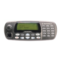
Figure 3 Transceiver Front View to the Standard Control Head Interface (12pins) and
Expansion Head Connector (40pins)
Pin Function Description
1 SCI_TX Serial Communication Interface TXD
2 SPEAKER + Analogue Speaker output +
3 Speaker - Analogue Speaker output -
4 GND Ground
5 DIG_IN1 (Ext. PTT) This is a digital input to trigger external PTT; active low; non
active high
6 5VD + 5V regulated
7 Handset_audio Handset audio
8 BUS + Either SBEP or Serial Communication Interface RXD
9 Int_Mic Microphone input
10 Flt_A+ Filtered A+
11 On_Off_Control_SV Radio On/Off Control shared with Control Head request
12 GND Ground
Table 18 Transceiver Pin Assignment of the Standard Control Head Interface (12 pins)
1
40
1
12
12 Pin Connector
40 Pin Connector
1
40
1
12
J0550
12 Pin Connector (Flex)
J0500
40 Pin Connector (Flex)
. . . . . . . . . . . . . . . . . . . . . . . . .
. . . . . . . . . .

 Loading...