Do you have a question about the Motorola MTM5 00 Series and is the answer not in the manual?
Details copyright ownership and restrictions for manual content and software.
Lists Motorola's registered trademarks and other company trademarks.
Information on RF energy awareness, control, and FCC occupational use requirements.
Details FCC regulations and compliance standards for RF exposure.
Guidelines for controlling RF exposure, operating instructions, and antenna installation.
Covers EMI, facilities, vehicles, driver safety, and general warnings.
Defines the manual's purpose, intended audience, and scope.
Lists available product information manuals and user guides.
Outlines Motorola's support services during and after the warranty period.
Identifies terminal models covered by the manual and their nomenclature.
Details technical specifications for the TETRA terminals.
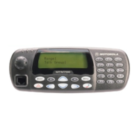
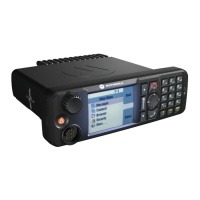
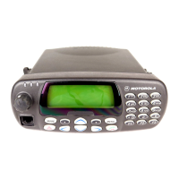
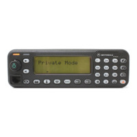
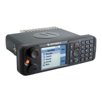
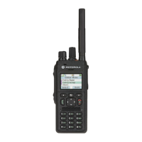
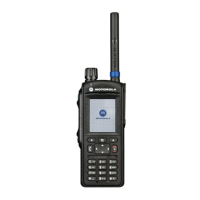
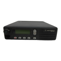
Describes different terminal models and their configurations.
Maps accessories to specific terminal models.
Provides a general introduction to the TETRA terminal and its capabilities.
Explains the digital modulation techniques used for voice and data transmission.
Details how voice is transmitted using DQPSK and TDMA technologies.
Describes the ACELP coding technique used for voice compression.
Covers Multi-Slot Packet Data (MSPD) and TETRA Enhanced Data System (TEDS).
Directs users to the CPS Start-up User Guide for programming instructions.
Introduces the chapter's content on testing procedures.
Details the test setup and procedures for the 380-430 MHz frequency range.
Introduces the chapter's topics on maintenance and repair.
Covers inspection and cleaning procedures for terminal maintenance.
Precautions for handling static-sensitive components during servicing.
General guidelines and techniques for performing repairs on the terminals.
Explains the need and procedure for pre-baking moisture-sensitive components.
Step-by-step instructions for disassembling and reassembling the terminal.
Lists recommended tools and aids for servicing the terminal.
Provides exploded views and parts lists for various terminal components.
Describes the service methodology for mobile units based on substitution.
Covers Level 1 and Level 2 maintenance procedures for the terminals.
Information on level 3 service partners and component-level repairs.
Guidance on replacing damaged parts with identical replacements.
Contact information for service centers in different regions.
Instructions for identifying and ordering spare parts and kits.
Details the electrical ratings and current consumption of the terminal.
Identifies fuses for power, ignition sense, and Y-cables with part numbers.
| Channel Spacing | 25 kHz |
|---|---|
| Operating Temperature | -30°C to +60°C |
| IP Rating | IP54 |
| Operating Voltage | 7.4V DC (Nominal) |
| TETRA Standard | ETSI TETRA standard |
| GPS | Yes |
| Connectivity | USB |
| Battery Life | Up to 12 hours |
| Frequency Bands | 380-400 MHz, 410-430 MHz, 450-470 MHz, 806-870 MHz |
| Frequency Range | 380-430 MHz, 410-470 MHz, 806-870 MHz |
