Test Setup & Testing for 380–430 MHz 5.1 - 1
CHAPTER 5.1
TEST SETUP & TESTING FOR 380–430 MHZ
Typical Test Setup
Before Testing
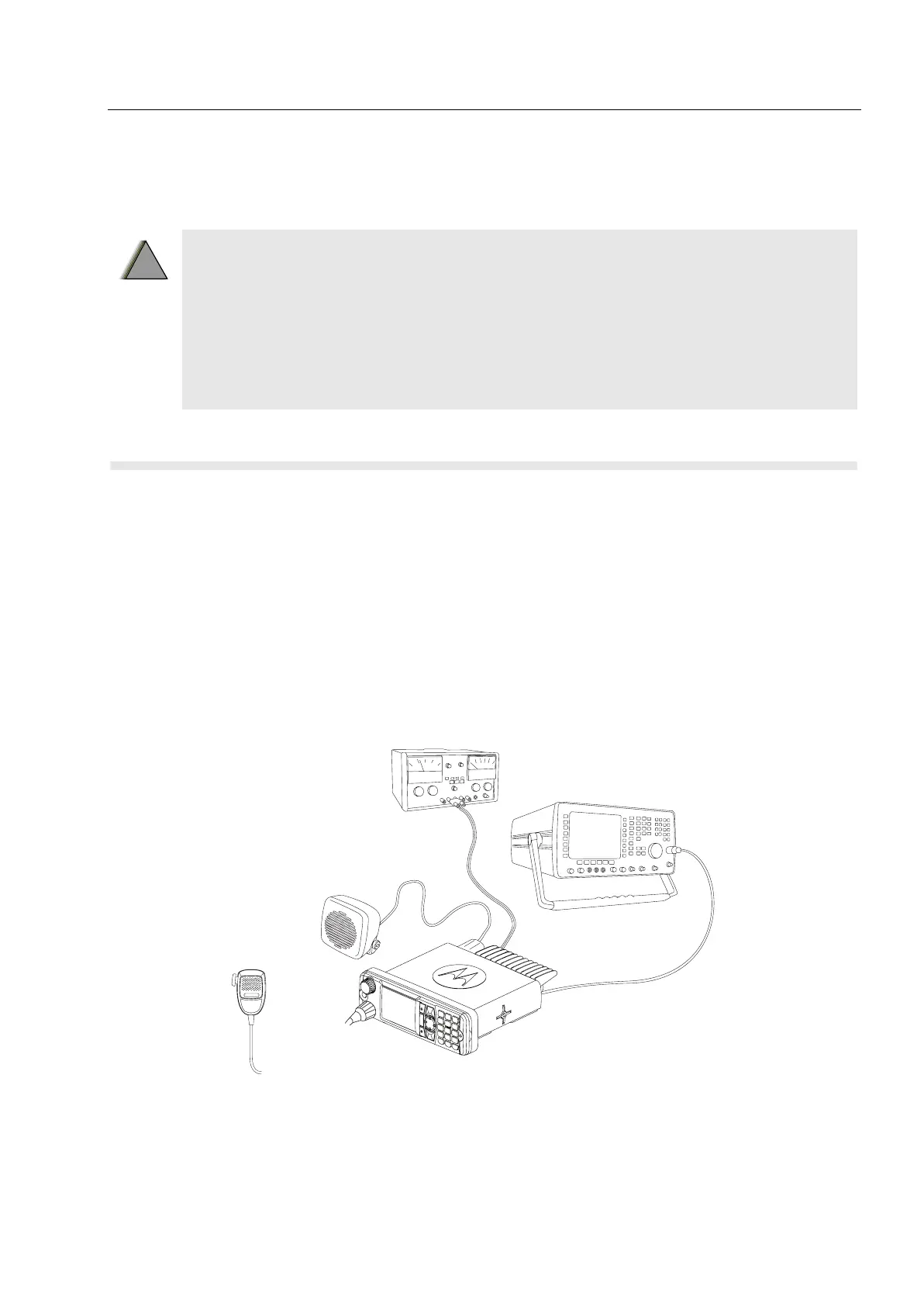
Carry out the following instructions before testing:
• Connect the DC cable to the DC connector on the terminal.
• Connect the other side of the DC cable to the DC output connector on the power supply
• Connect an RF cable to the N-type RF Connector of the IFR.
• Connect the other side of the RF cable to the antenna connector on the terminal.
• Set the DC voltage on the power supply to 13.2 Volts.
• Switch on the terminal.
Figure 5.1-1 Typical Test Setup
Any level 3 repairs can deeply affect the performance of the
MTM5400/MTM800 FuG with Enhanced Control Head terminal and may
cause a new tuning procedure.
This tuning procedure can only be applied by certain authorized Motorola
depots where the appropriate TEST&TUNE EQUIPMENT is available.
The appropriate TEST&TUNE EQUIPMENT is a special automated test
equipment which is only available at some Motorola factories and Motorola
repair centers.
!
W A R N I N G
!
C
C
C
C
C
C
C
C
C
C
C
C
C
C
C
C
C
C
C
C
C
C
C
C
C
C
C
C
C
C
C
C
C
C
C
C
C
C
C
IFR2968
N-Type
RF Connecto
RF-Cable
Speaker
Microphone
Power Supply
13.2V 5A
DC Cable
BNC-Type
RF Connector

 Loading...


