5.1 - 2 Test Setup & Testing for 380–430 MHz
Test Equipment
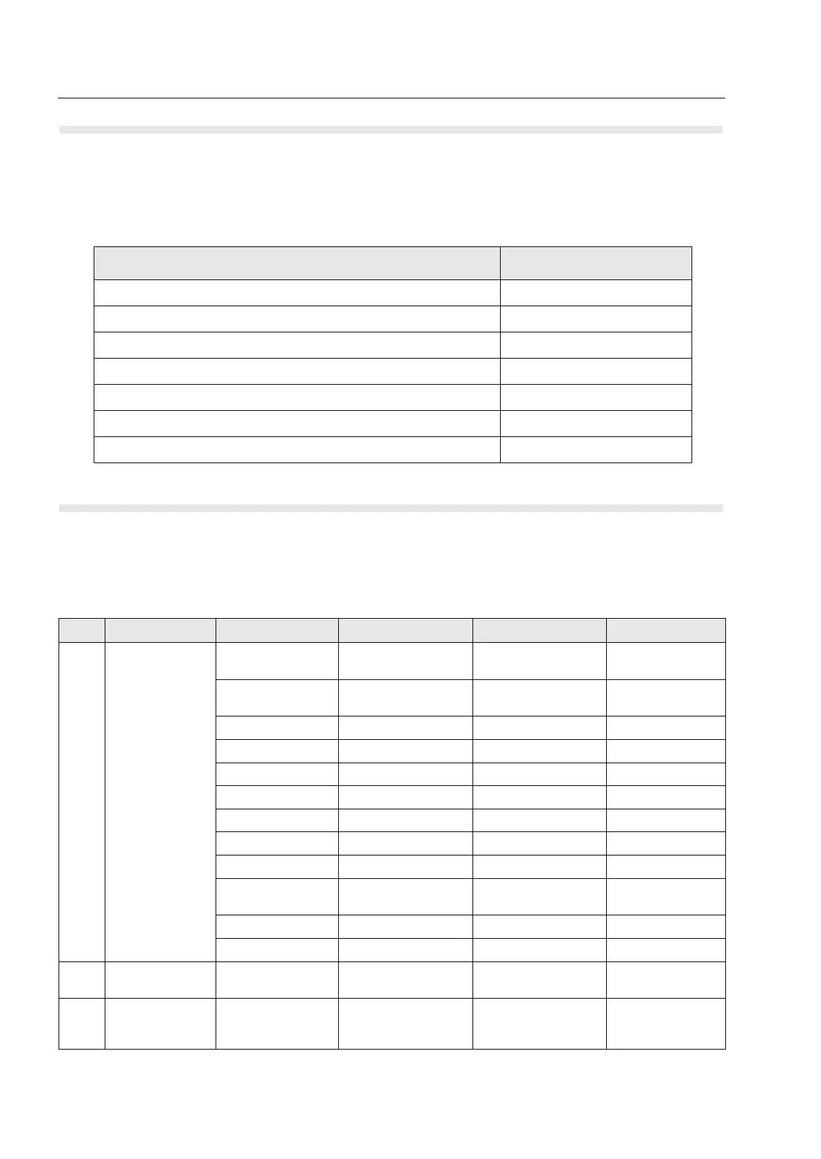
The table below lists the special test equipment required for servicing TETRA mobile terminals.
Test Check List
The following table summarises the required test setups.
Table 5.1-1 Test Equipment
Name Part Number
Digital Multimeter R1072_
220V Power Supply R1011_/220V
TETRA SVC MON. MOBILES ONLY WADN4161A
TETRA SVC MON. MOB.+ DIR.MODE WADN4163A
TETRA SVC MON. MOB.+ BASE ST. WADN4164A
TETRA SVC MON. MOB.+ BASE ST. + DIRECT MODE WADN4173A
TETRA SVC MON. MOB.+ DIR.MODE + MPT1327/1343 WADN4233A
Table 5.1-2 Test Setup
No. Test Name Test Setup Terminal Setup Test Conditions Limits
1. IFR System Setup
and Manual Test
Screen
Control Channel For 380–430 MHz
terminal: 3605
Traffic Channel For 380–430 MHz
terminal: 3605
Time Slot 3
Country Code 234
Network Code 2392
Base Color 1
Location Area 224
Min Rx Level -110dBm
Max Tx Level 40dBm (10W)
Access
Parameter
-33dBm
Mobile Power 40dBm (10W)
Burst Type Normal
2. Base Station
Registration
RF Gen Level For 380–430 MHz
terminal: 390.125 MHz
-90dBm
3. Receiver RSSI RF Gen Level Cells Info
RSSI
TRACE
-90dBm

 Loading...


