Maintenance 6 - 13
SIM Dust Cover Assembly
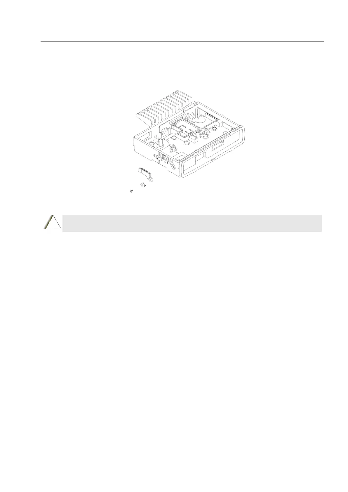
1. Place the SIM dust cover in place before placing the SIM dust cover plate. Tighten the screw
with 0.23 Nm (2 lbin) using a Phillips screwdriver.
Figure 6-13 SIM Dust Cover Assembly
Enhanced Control Head Fitting
1. Connect the flex to the top small connector in the terminal with the 'dot' or 'O' facing upwards
and away from the terminal; make sure the 'dot' or 'O' aligns with the 'O' on the terminal. The
flex must be fully pushed into the connector.
2. Check that the back housing O-ring seal is undamaged, and fits properly in the groove.
Replace the seal, if it is damaged (refer to the exploded view diagrams and parts list).
3. Fit the back housing to the Enhanced Control Head. Ensure that the tags on the back housing
align with the snap catch grooves on the Enhanced Control Head. Press the back housing
until it snaps into place.
4. Check that the terminal chassis O-ring seal is undamaged, and fits properly in the groove on
the chassis assembly. Replace the seal, if it is damaged.
CAUTION: Ensure that the dust cover is flushed with the diecast surface. If the dust cover is
NOT flushed properly, sealing failure may occur.
!

 Loading...


