6 - 12 Maintenance
9. Tighten the two PCB screws with 1.9 Nm (17 lbin) using a T20 TORX
TM
driver following the
sequence specified on the PCB.
10. Connect the GPS MCX connector to the board’s GPS connector.
11. Connect the plastic accessory connector housing.
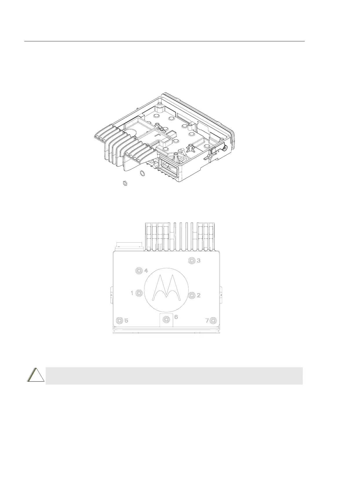
Figure 6-11 Assembling the GPS Cable Bulkhead
12. Secure the diecast cover, and tighten the seven screws with 1.9 Nm (17 lbin) following the
sequence shown using a T20 TORX
TM
driver.
Figure 6-12 Screw Sequence for Tightening the Diecast Cover
13. Insert the SIM card (if applicable), and reattach the SIM dust cover.
14. Refit the top plastic cover over the assembled terminal chassis. Press cover down until it
snaps into place.
CAUTION: Ensure that the dust cover is flushed with the diecast surface. If the dust cover is
NOT flushed properly, sealing failure may occur.
!

 Loading...


