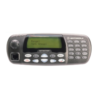
TROUBLESHOOTING CHARTS (800MHz) MTM700 Mobile Radio / Detailed Service Manual 9.2 - 17
Synthesizer & VCO Troubleshooting
NO
NO
Is the
frequency
787.175 MHz
@ +3dBm
YES
Measure the RF level at the pres-
caler input on C5338.
YES
Is the frequency at
TP5701 787.175 MHz
@ -0dBm
NO
Synthesizer and RX VCO are
OKAY.
For TX issues check Escort. For RX
issues check Receiver.
Problem still
exists?
YES
YES
Are bias volt-
ages
correct?
NO
YES
Is voltage at
C5301
@ about 5.3V?
Make sure U5701 is pow-
ered (5V on pins 14 and
18), and the surrounding
components are in place.
Measure Q5712 bias volt-
ages:
• Base 2.3V,
• Collector 4.3V, and
• Emitter 1.7V.
Fix problem with
Q5712, or bias
components.
Check Loop filter components (C5305,
R5304, C5305, R5302, and C5301).
Is RXH Line
@ 5V?
YES
Measure the RF
level at TP5701.
Make sure Pin 19 and 20 of
U5701 are close to 0V.
Check C5740.
Replace U5701.
Is 787.175 MHz
present at pin 8
of U5701?
Measure Q5701 bias
voltages:
• Base 0.7V,
• Collector 3.3V,
• Emitter 0V.
Fix problem with
Q5701, or bias com-
ponents.
NO
YES
Check Q5301 for solder-
ing defects. Make sure
that Pin 48 of U5331 is
@ 5V.
NO
Tetra Com Script for Rx Test:
TEST_ENTER
DELAY 10
Check for “Radio HW is Ready”
MODE IDLE
FREQ RF 860.525
L1TIMER ON
AVE 10
MODE RSSI
GO
Use STOP to terminate RSSI reading

 Loading...