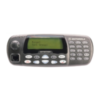
CONNECTOR PIN FUNCTIONS MTM700 Mobile Radio / Detailed Service Manual A - 11
Pin Name Function Input/Output Description
1 N.C. Not connected.
2 EMC_KEYLOAD Keyload In Used for encryption key loading.
3 RESET SB9600
Reset
In/Out This is part of the Motorola Bus to connect external
devices.
4 BUS- SB9600 Bus- In/Out This is part of the Motorola Bus to connect external
devices.
5 N.C. Not connected
6 N.C. Not connected
7 GND Ground In/Out Used as ground.
8 RX_AUDIO Received
Audio
In The nominal input level of this low level audio is 80mV.
The input impedance is 560 ohms.
Used as an audio for earpiece.
9 MIC_ON_OFF Mic On/Off In This Microphone input is parallel to the Microphone
input of the control head microphone connector.
The nominal input level is 80 mV.
The DC impedance is 20 k
Ω and the AC impedance is
560 ohms.
Pulling this line low (below 0.6 VDC) will switch the
radio on or off, depending of the previous state.
Note: Only one microphone should be active at the
same time, to make sure that no on/off function is
detected by the radio.
10 N.C. Not connected.
11 EMC_KEYFAIL Keyfail In/Out Used for encryption data.
12 N.C. Not connected.
13 GND Ground In/Out Used as ground.
14 BUSY SB9600 Busy In/Out This is part of the Motorola Bus to connect external
devices.
15 BUS+ SB9600 Bus+ In/Out This is part of the Motorola Bus to connect external
devices.
16 N.C. Not connected
17 A+ Battery In The voltage is 13.2 V nominal. Available when the
radio is connected to the battery.
18 SWB+ Battery Switch In The voltage is 13 V, nominal. It is available when the
radio is switched on.
Table 26 Motorcycle Control Head Connector Pin Functions

 Loading...